DevLab: I2C BMM150 Magnetometer Sensor
Professional electronic component
Product Overview
The BMM150 is a triaxial digital geomagnetic sensor optimized for low-power, high-precision applications. Engineered by Bosch Sensortec, it provides absolute magnetic field measurements along the X, Y, and Z axes, suitable for electronic compassing and inertial navigation tasks. The device integrates seamlessly via I²C or SPI, ensuring compatibility with a wide range of host controllers, including Arduino, ESP32, and Raspberry Pi. Its compact form factor and minimal power profile make it ideal for space- and energy-constrained systems such as wearables, mobile robotics, and UAVs. Built-in compensation algorithms correct soft-iron and hard-iron distortions, supporting reliable heading estimation in real-world environments. When used in conjunction with accelerometers and gyroscopes, the BMM150 enables robust 9DoF sensor fusion for advanced motion tracking and orientation systems.
Product Views
SPECIFICATIONS
POWER SUPPLY
CONNECTIVITY
TECHNICAL FEATURES
TECHNICAL SPECIFICATIONS
TYPICAL APPLICATIONS
| Application | Description |
|---|---|
| Electronic Compass | Detects Earth’s magnetic field to determine the device orientation. |
| Inertial Navigation (INS) | Integrates with accelerometers and gyroscopes to improve position and orientation estimation. |
| Augmented Reality (AR) | Dynamically adjusts AR content on smart devices based on precise orientation data. |
| Metal Detection / Proximity Sensing | Monitors magnetic field variations to detect metallic objects and machinery anomalies. |
| Mobile Robotics and Drones | Provides reliable heading information, essential for indoor navigation and autonomous operation. |
| Wearables and Portable Devices | Enhances personal navigation in smartwatches, fitness trackers, and other portable devices. |
| Indoor Geolocation | Improves indoor positioning accuracy by compensating for sensor drift and interference. |
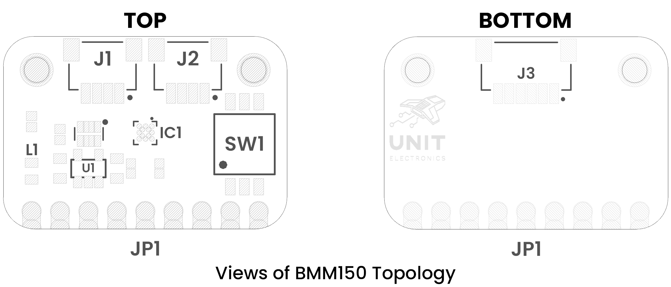
Component Reference
| Ref. | Description |
|---|---|
| IC1 | BMM150 Magnetometer |
| U1 | AP2112K 3V3 Regulator |
| L1 | Power On LED |
| SW1 | Dip Switch for Mode and Address Selector |
| J1 | QWIIC Connector (JST 1mm for I2C) |
| J2 | QWIIC Connector (JST 1mm for I2C) |
| J3 | JST Connector 1mm Pitch for SPI |
| JP1 | 2.54mm Castellated Holes |