Hardware Overview
Technical Specifications
- Microcontroller: PY32f003L24D6TR (ARM Cortex-M0)
- Core Architecture: 32-bit ARM Cortex-M0
- Clock Speed: 24 MHz
- Flash / RAM: 16 KB Flash, 2 KB SRAM
- Wireless: None
- Interfaces: I2C, SPI, UART, ADC
- Connector: QWIIC + Pin Headers
- Power:
- Input via USB-C: 5V
- Regulated Output: 3.3V
- Battery Support: No
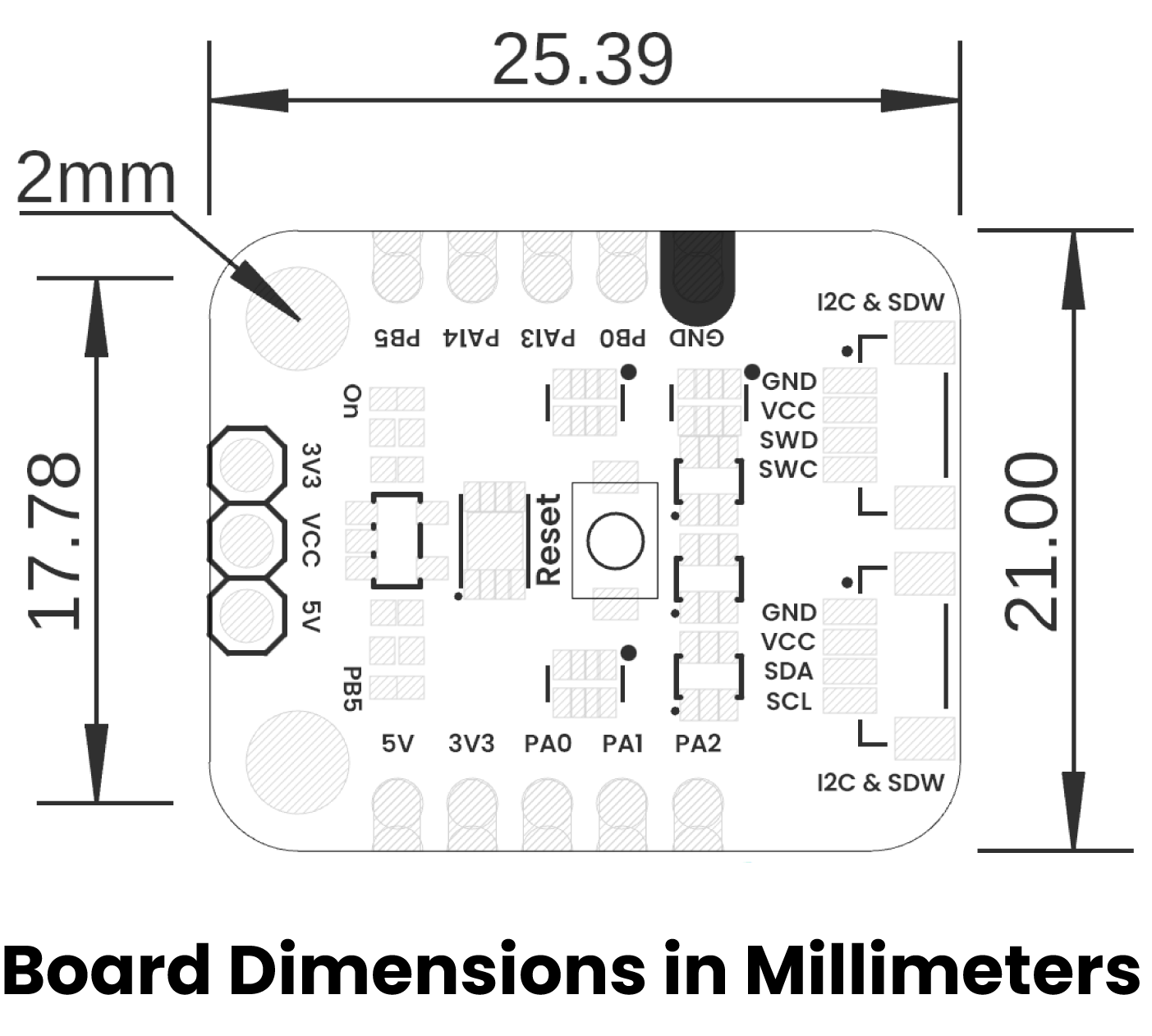
Pinout
Pinout Details
| Pin Label | Function / Notes |
|---|---|
| VCC | Power Input |
| GND | Ground |
| PA0 | USART2_TX MISO |
| PA1 | USART2_RX SCK |
| PA2 | ADC_IN2 CS |
| PB0 / PF2 | GPIO / NRST |
| PB5 | LED Built In / GPIO / MOSI |
| PA13 / PB6 | SWDIO / I2C_SCL |
| PA14 / PA10 | SWCLK / I2C_SDA |
Connectivity Options
- I2C: JST 1mm QWIIC connector (Power + I2C lines)
- SPI: JST 1mm connector (Power + SPI lines)
- GPIO: 2x 4-pin headers for general-purpose I/O
- SWD: Dedicated pins for programming and debugging
Board Dimensions
Board Topology
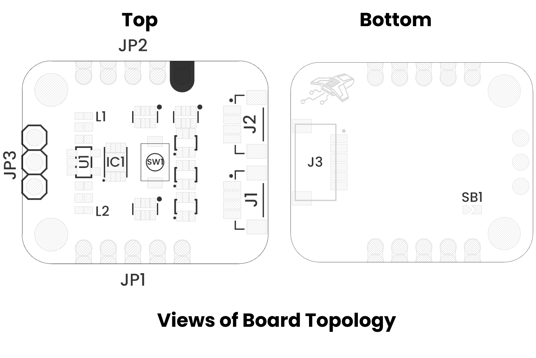
| Ref. | Description |
|---|---|
| IC1 | PY32f003L24D6TR Microcontroller |
| U1 | AP2112K 3.3V Regulator |
| SW1 | Reset Push Button |
| L1 | Power On LED |
| L2 | Built In LED to PB5 |
| J1 | JST 1mm Connector for I2C or JTAG |
| J2 | JST 1mm Connector for I2C or JTAG |
| J3 | JST 1mm Connector for SPI |
| JP1 | Header for GPIOs |
| JP2 | Header for GPIOs |
| JP3 | Header for Power Supply Selection |
| SB1 | Solder Bridge to Enable LED Built In |