# Hardware

<div align="center">

<a href="./unit_sch_V_0_1_2_ue0072_touch_dot_s3.pdf"><img src="resources/img/Schematics_icon.jpg?raw=false" width="450px"><br/>Schematics</a>

</div>

---

## PINOUT

<div align="center">
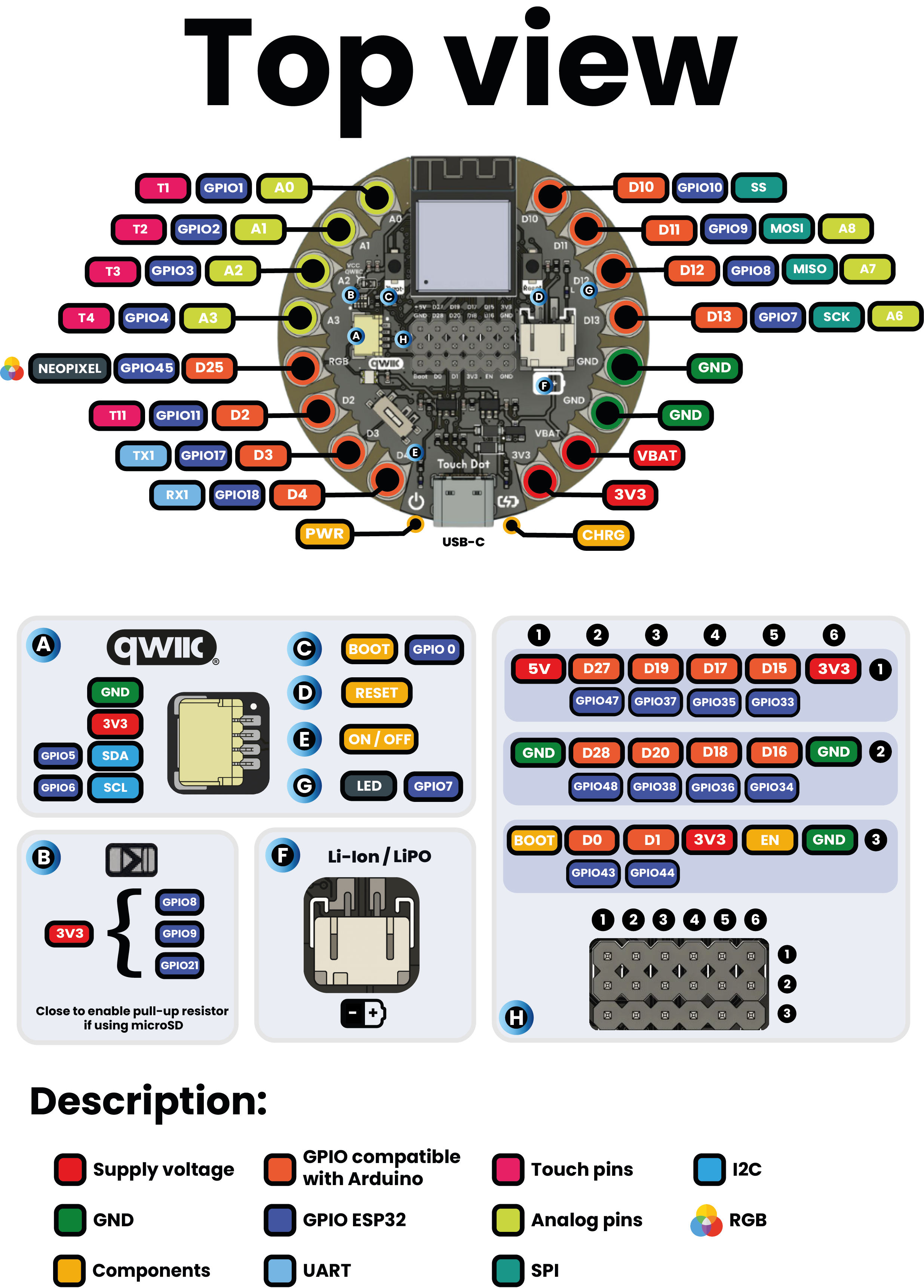
    <a href="resources/unit_pinout_top_v_0_2_0_ue0072_touch_dot_s3_en.png"><img src="resources/unit_pinout_top_v_0_2_0_ue0072_touch_dot_s3_en.png" width="500px"><br/>Top view</a>

<br/><br/>

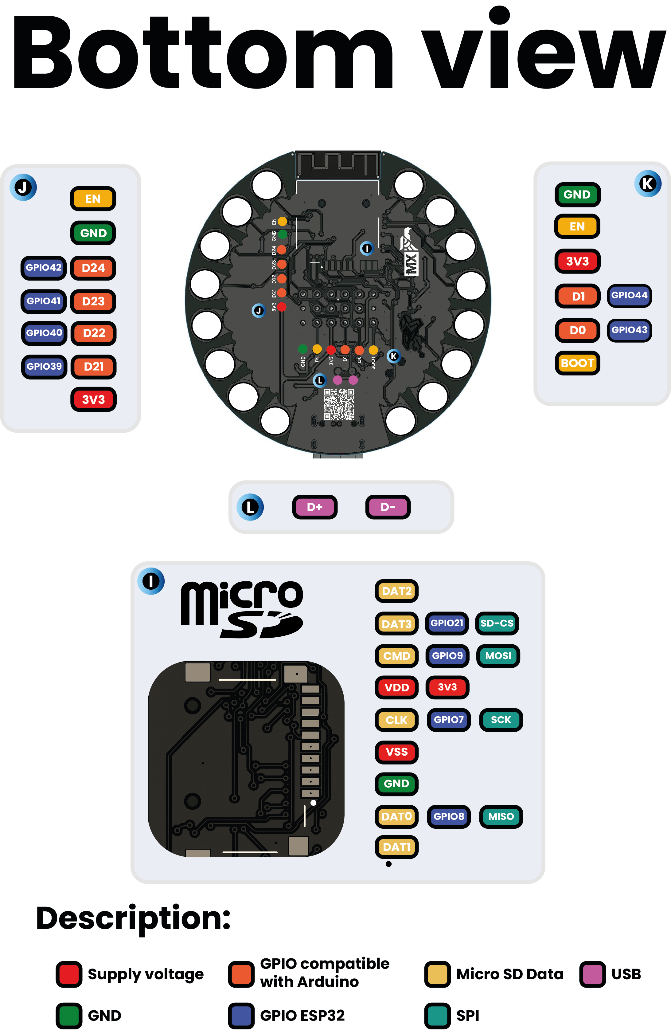
<a href="resources/unit_pinout_bottom_v_0_2_0_ue0072_touch_dot_s3_en.png"><img src="resources/unit_pinout_bottom_v_0_2_0_ue0072_touch_dot_s3_en.png" width="500px"><br/>Bottom view</a>


| **Group**     | **Available Pins** | **Suggested Use**                      |
|---------------|--------------------|----------------------------------------|
| **GPIO**      | D2 to D13          | Sensors, actuators                     |
| **UART**      | Tx and Rx          | Serial communication                   |
| **TouchPad**  | T1 to T11          | Capacitive sensors for touch detection |
| **Analog**    | A0 to A8           | 12-bit (0–4095) resolution             |
| **SPI**       | Optional           | Displays, additional memory            |

</div>

---

## Dimensions

<div align="center">

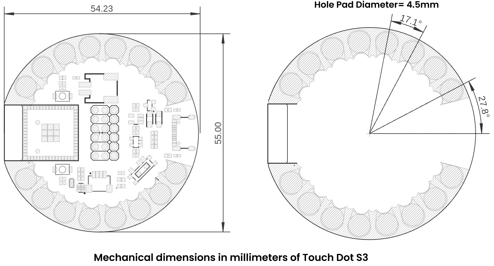
<a href="#"><img src="./resources/unit_dimension_V_0_1_2_ue0072_Touch-Dot-S3.png" width="500px"><br/>Dimension</a>
</div>

---

## Topology

<div align="center">

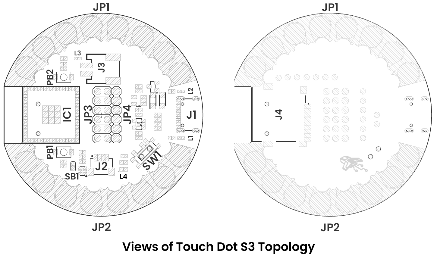
<a href="#"><img src="./resources/unit_topology_V_0_1_2_ue0072_Touch-Dot-S3.png" width="500px"><br/>Topology</a>

| Ref.  | Description                                                                 |
|-------|-----------------------------------------------------------------------------|
| IC1   | Espressif ESP32-S3                                                          |
| U1    | AP2112K 3.3V LDO Voltage Regulator                                          |
| PB1   | Boot Push Button                                                            |
| PB2   | Reset Push Button                                                           |
| SW1   | Power On Switch                                                             |
| L1    | Power On LED                                                                |
| L2    | Charge On LED                                                               |
| L3    | Built-in LED (GPIO 6 or D13)                                                |
| L4    | WS2812B-2020 LED                                                            |
| SB1   | Solder bridge to enable QWIIC VCC                                           |
| J1    | Male USB Type-C Connector                                                   |
| J2    | Low-power I2C QWIIC JST Connector                                           |
| J3    | PH2.0 mm Pitch Battery Connector                                            |
| J4    | Micro SD Slot                                                               |
| JP1   | Sewable Pads                                                                |
| JP2   | Sewable Pads                                                                |
| JP3   | GPIO, system, and power supply pin headers                                  |
| JP4   | GPIO, system, and power supply pin headers                                  |
</div>