Analog to Digital Converter (ADC)#
The PY32F003L24D6TR microcontroller integrated into the DevLab Development Board features a 12-bit Analog to Digital Converter (ADC) that provides high-resolution analog signal measurement capabilities. The ADC supports multiple input channels, allowing users to connect various analog sensors and devices for data acquisition.
Overview#
The PY32F003 microcontroller features a 12-bit Analog-to-Digital Converter (ADC) at the hardware level, providing a theoretical range of 0–4095.
However, when using the Arduino core, the function analogRead() is limited to 10-bit resolution by default, returning values in the range 0–1023. This behavior is intentional and follows the traditional Arduino API for compatibility with legacy boards (e.g., AVR-based Arduino UNO).
Default Behavior#
int value = analogRead(PA2);
// Range: 0 – 1023 (10-bit)
Key characteristics:
Default ADC resolution: 10 bits
Maximum value: 1023
Hardware ADC resolution (internal): 12 bits
Changing ADC Resolution#
If supported by the Arduino core, the ADC resolution can be modified using:
analogReadResolution(12);
Example:
void setup() {
  Serial.begin(115200);
  analogReadResolution(12);
}

void loop() {
  int value = analogRead(PA2);
  Serial.println(value);  // Range: 0 – 4095
}
Warning
Some Arduino cores for PY32 devices may ignore analogReadResolution() and always return 10-bit values.
Compatibility Note#
If analogReadResolution(12) is not implemented in the core:
analogRead()will always return 10-bit valuesThe ADC hardware still operates at 12 bits internally
The result is scaled or truncated by the core
A simple approximation can be done manually:
int adc10 = analogRead(PA2);
int adc12 = adc10 << 2;  // Approximate 12-bit value
Summary#
Item |
Value |
|---|---|
Hardware ADC |
12-bit |
Arduino analogRead() default |
10-bit |
Output range (default) |
0–1023 |
Output range (12-bit) |
0–4095 |
Recommended for precision |
Use HAL / low-level ADC |
Recommendation#
For applications requiring full ADC precision, direct ADC access via HAL or low-level drivers is recommended instead of the Arduino abstraction layer.
Example Usage#
Complete ADC Example#
This example demonstrates ADC reading, LED control, and serial communication:
/* ===============================
 *  PY32F003 – ADC + LED + Serial
 * ===============================
 * ADC  : PA2
 * LED  : PB5
 * UART : PA0 (TX) / PA1 (RX)
 */

int sensorPin = PA2;   // ADC input
int ledPin    = PB5;   // LED output
int sensorValue = 0;

void setup() {
  // GPIO
  pinMode(ledPin, OUTPUT);
  analogReadResolution(12);

  // Serial (PA0 = TX, PA1 = RX)
  Serial.begin(115200);
  delay(100);

  Serial.println("=== PY32F003 ADC + Serial + LED ===");
  Serial.println("ADC on PA2 | LED on PB5");
  Serial.println("Type something for echo...");
}

void loop() {
  /* ===== ADC READ ===== */
  sensorValue = analogRead(sensorPin);  // 0–4095 (12-bit)

  /* ===== SERIAL OUTPUT ===== */
  Serial.print("ADC Value: ");
  Serial.println(sensorValue);

  /* ===== LED BLINK BASED ON ADC ===== */
  digitalWrite(ledPin, HIGH);
  delay(sensorValue / 4);   // scale delay to be reasonable
  digitalWrite(ledPin, LOW);
  delay(sensorValue / 4);

  /* ===== SERIAL ECHO ===== */
  while (Serial.available()) {
    char c = Serial.read();
    Serial.write(c);   // echo back
  }
}
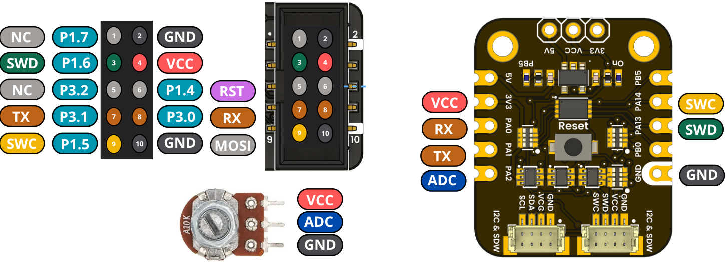
Pin Configuration#
Function |
Pin |
|---|---|
ADC Input |
PA2 |
LED Output |
PB5 |
UART TX |
PA0 |
UART RX |
PA1 |
Note
Make sure to connect your analog sensor to PA2 with appropriate voltage levels (0-3.3V).