TEMT600 Ambient Light Sensor
Introduction
The TEMT600 Ambient Light Sensor Development Board is a compact module built around the Vishay TEMT600 phototransistor. It provides a linear analog voltage proportional to ambient light intensity, making it ideal for display back-light control, energy-saving systems, photographic exposure adjustment, and environmental monitoring applications.
📦 Overview
| Feature | Description |
|---|---|
| Sensor Type | Ambient Light Sensor (TEMT600) |
| Supply Voltage | 3.3V - 5V |
| Interface | Analog Output |
| Light Sensitivity | 0.2 to 1000 lux (typical) |
| Response Time | ~100 ms |
| Operating Temperature | -40°C to +85°C |
| Connector Type | JST 1.0mm 4-pin |
🧪 Use Cases
- Automatic display brightness adjustment
- Photographic light metering
- Smart home & IoT light sensing
- Plant/garden lighting control
- Wearable/light-level logging
- Data-logging & environmental sensing
📚 Resources
📝 License
All hardware and documentation in this project are licensed under the MIT License.
Please refer to LICENSE.md for full terms.
Hardware Overview
KEY TECHNICAL SPECIFICATIONS
🔌 CONNECTIVITY (Conectividad)
| Interface | Details |
|---|---|
| Primary Interface | GPIO (Analog) |
| Connector Type | JST 4-pin 1.0mm |
| Logic Levels | VCC |
⚙️ Technical Specifications
| Pin | Symbol | Type | Description |
|---|---|---|---|
| 1 | GND | Power | Ground reference (connect to MCU GND) |
| 2 | VCC | Power | +3.3 V to +5 V supply voltage |
| 3 | D0 | Analog | voltage ∝ ambient light; connect to an ADC input of your MCU |
Note: Do not exceed 5 V on VCC. SIO swings between 0 V (dark) and VCC (bright).
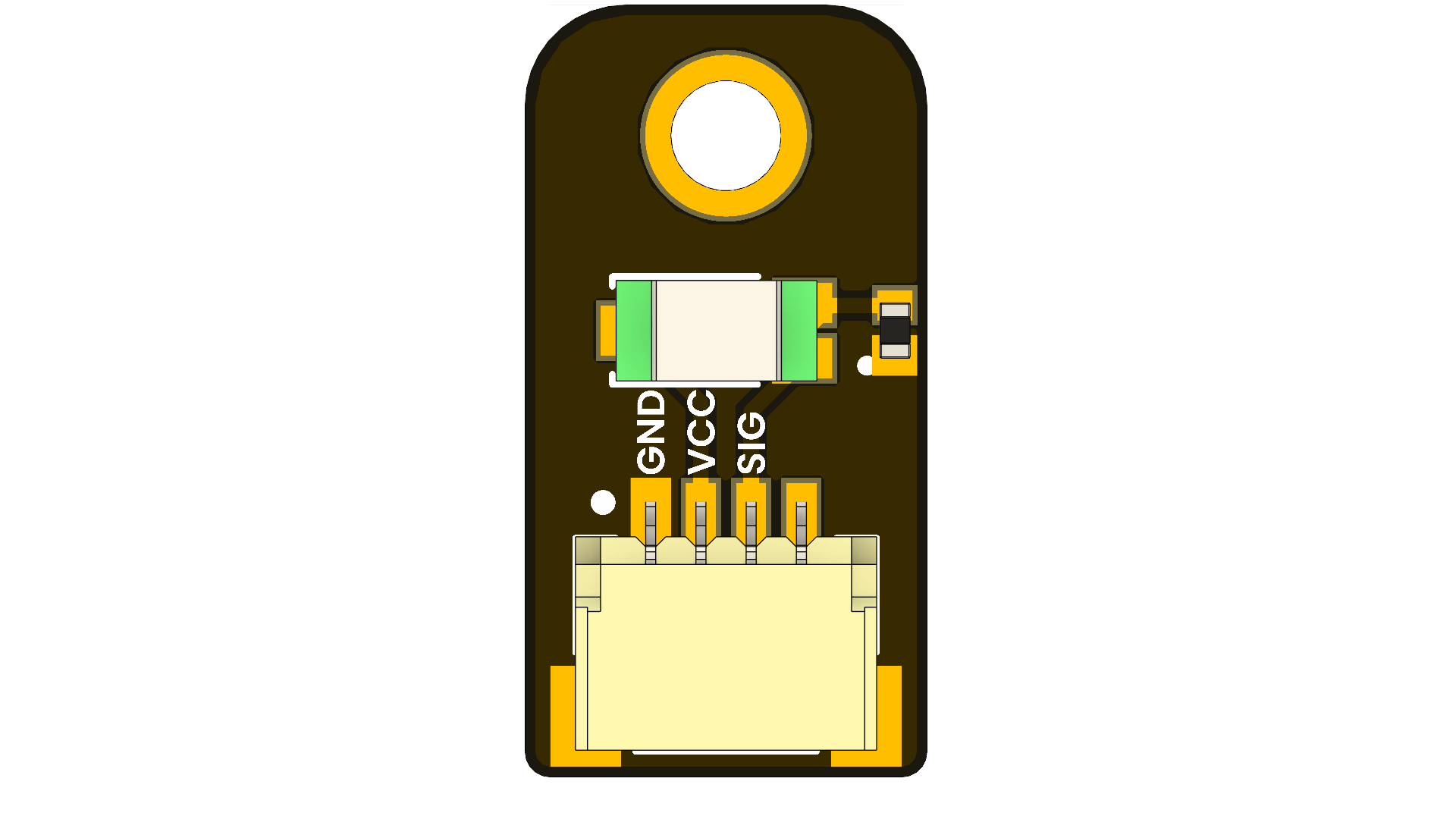
🔌 Pinout
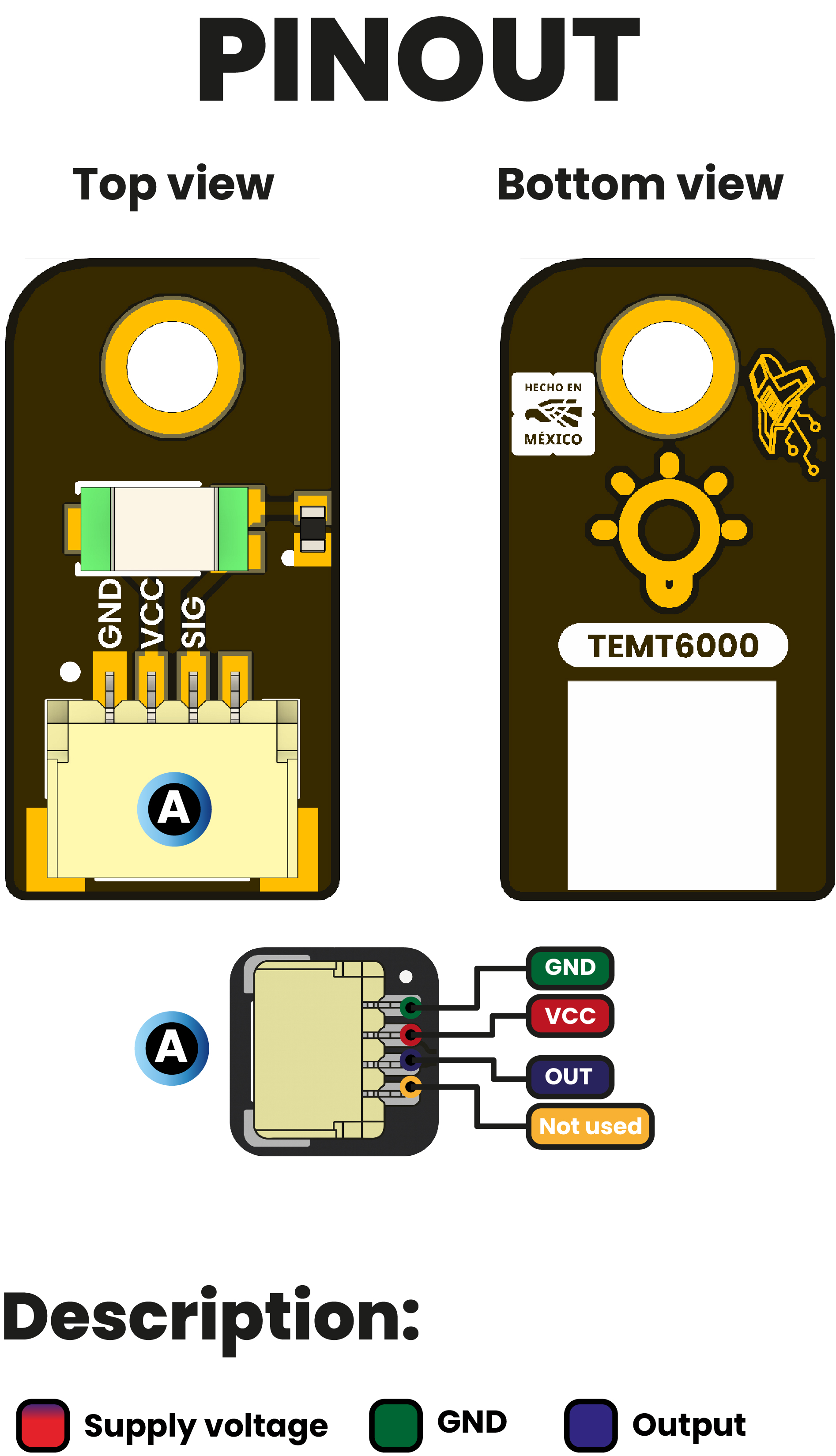
Pinout Details
| Pin Label | Function | Notes |
|---|---|---|
| VCC | Power Supply | 3.3V or 5V, depending on design |
| GND | Ground | Common ground reference |
| D0 | Data Signal | Digital input/output signal |
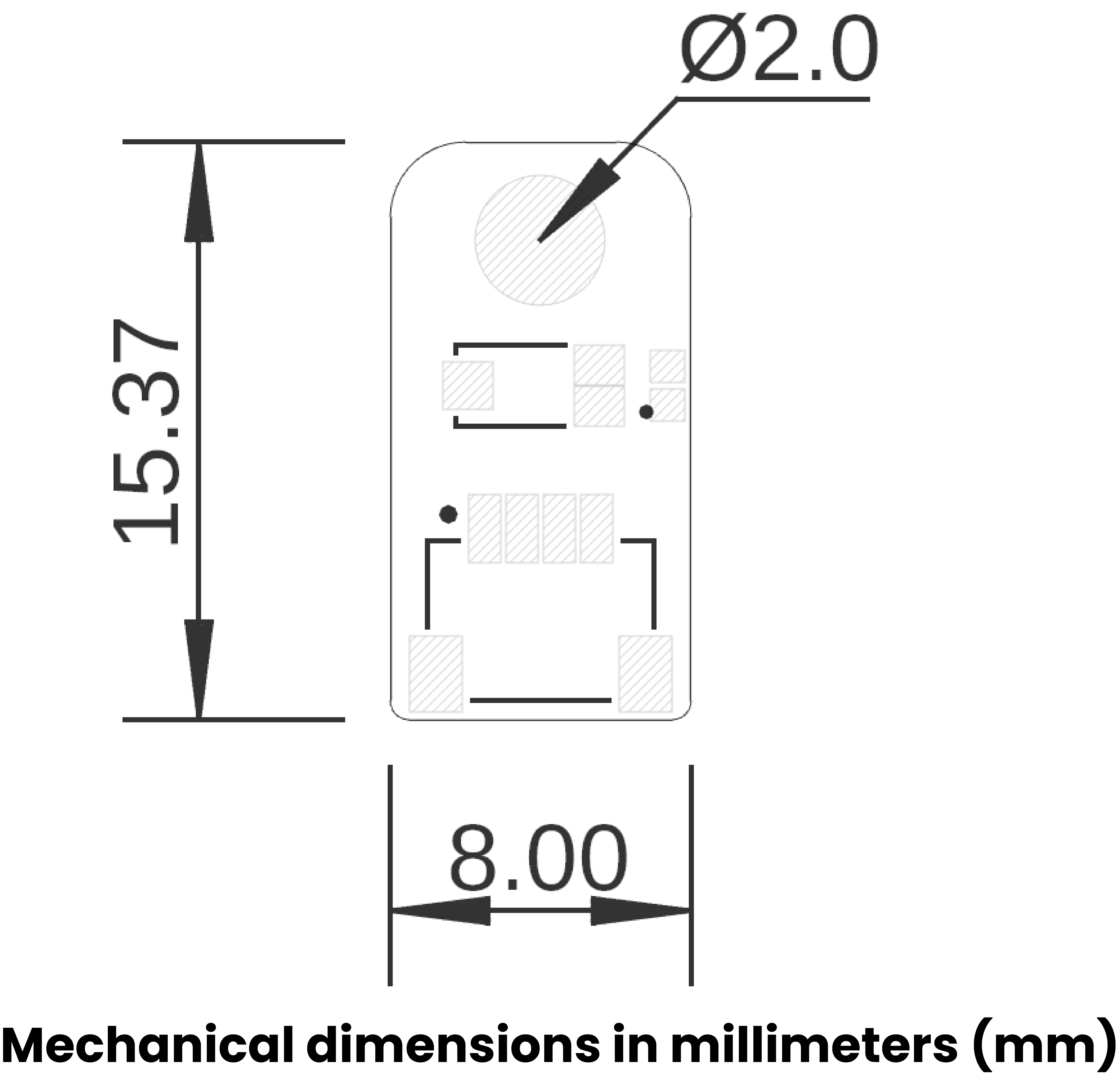
📏 Dimensions
📃 Topology
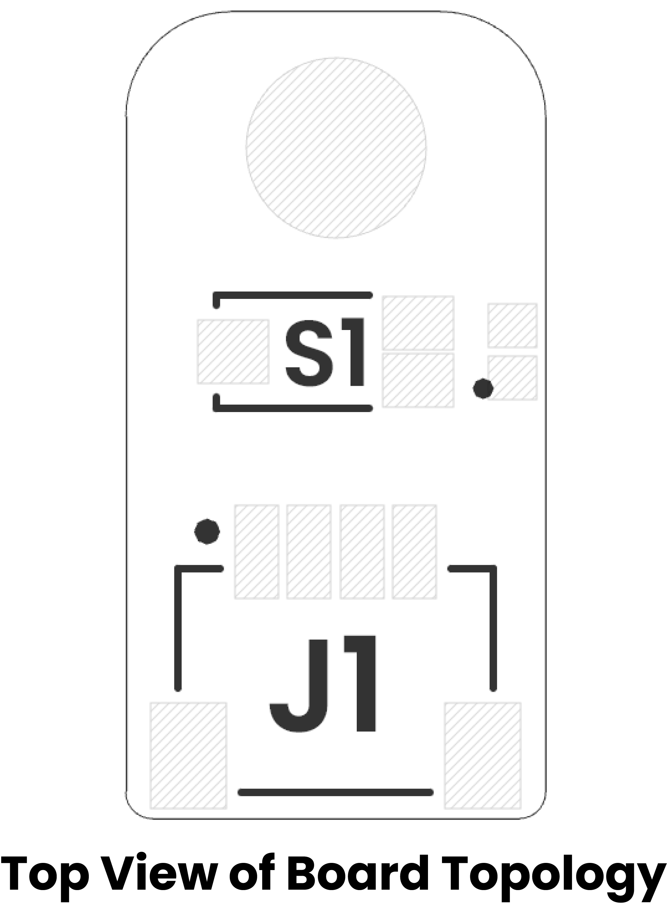
| Ref. | Description |
|---|---|
| S1 | TEMT6000 Ambient Light Sensor |
| J1 | JST 1 mm pitch Connector for Power Supply and Signal |
Reference
Key Technical Specifications
🔌 CONNECTIVITY (Conectividad)
| Interface | Details |
|---|---|
| Primary Interface | GPIO (Analog) |
| Connector Type | JST 4-pin 1.0mm |
| Logic Levels | VCC |
️ Technical Specifications
| Pin | Symbol | Type | Description |
|---|---|---|---|
| 1 | GND | Power | Ground reference (connect to MCU GND) |
| 2 | VCC | Power | +3.3 V to +5 V supply voltage |
| 3 | D0 | Analog | voltage ∝ ambient light; connect to an ADC input of your MCU |
Note: Do not exceed 5 V on VCC. SIO swings between 0 V (dark) and VCC (bright).
Pinout
Pinout Details
| Pin Label | Function | Notes |
|---|---|---|
| VCC | Power Supply | 3.3V or 5V, depending on design |
| GND | Ground | Common ground reference |
| D0 | Data Signal | Digital input/output signal |
Dimensions
Topology
| Ref. | Description |
|---|---|
| S1 | TEMT6000 Ambient Light Sensor |
| J1 | JST 1 mm pitch Connector for Power Supply and Signal |
Reference
Getting Started
This guide provides instructions on how to use the TEMT6000 ambient light sensor with an Arduino-compatible board (like the Pulsar ESP32 C6) or a MicroPython-compatible board (like the DualMCU) to detect ambient light levels and display the results via the Serial Monitor.
Hardware Requirements
- Microcontroller Board: ESP32 or compatible
- Sensor: TEMT6000 Ambient Light Sensor
- Cabling: JST connector
Wiring Instructions
- VCC: Connect to 5 V (match your board’s logic level)
- GND: Connect to GND (common ground)
- SIG: Connect to GPIO12 (digital input on the microcontroller)
Software Setup
- Install the Arduino IDE or Thonny IDE.
- Create a new project and paste the code from
light_sensor.ino(Arduino) orlight_sensor.py(MicroPython). - Upload the code to your board.
- Open the Serial Monitor at 115200 baud to view sensor output.
How to Use
-
Power up the board with the uploaded code.
-
Check the Serial Monitor for messages:
- If light is detected:
🔆 Light detected (HIGH) - If no light is detected:
🌑 No light (LOW)
- If light is detected:
-
Testing:
- Cover the sensor to simulate darkness.
- Shine a light on the sensor to simulate brightness.
- Observe changes in the Serial Monitor output.
Troubleshooting
- No Output in Serial Monitor:
- Ensure the correct COM port is selected.
- Verify baud rate is set to 115200.
- Incorrect Readings:
- Check wiring connections.
- Ensure the sensor is receiving power.
- Sensor Not Responding:
- Test with a different GPIO pin.
- Board Not Recognized:
- Install necessary drivers for your microcontroller board.
Additional Resources
License
This project is licensed under the MIT License. See the LICENSE file for details.
Examples
Arduino/C++ Examples
The following examples demonstrate various features of this development board.
⚡ light_sensor
#include <Arduino.h>

const int SENSOR_PIN = 12;  // GPIO12 connected to the module’s digital output

void setup() {
  // Initialize Serial at 115200 baud
  Serial.begin(115200);
  while (!Serial) { }  // Wait for Serial (on some boards)

  // Configure GPIO12 as digital input with internal pull-down
  pinMode(SENSOR_PIN, INPUT_PULLDOWN);

  Serial.println("Reading Qwiic module in digital mode (GPIO12)...");
}

void loop() {
  int state = digitalRead(SENSOR_PIN);  // Read 0 (LOW) or 1 (HIGH)

  if (state == HIGH) {
    Serial.println("🔆 Light detected (HIGH)");
MicroPython Examples
The following MicroPython examples demonstrate usage with microcontrollers.
🐍 light_sensor_adc
from machine import Pin, ADC
import time

# Configure GPIO6 as ADC input (ESP32C6)
light_sensor = ADC(Pin(6))

# Depending on your board, you may need to set attenuation for higher voltage range
# For ESP32: attenuation can be 0db (0–1V), 2.5db (0–1.34V), 6db (0–2V), 11db (0–3.6V)
try:
    light_sensor.atten(ADC.ATTN_11DB)   # Full range ~3.6V
except:
    pass  # Some ports (like RP2040) don't need this

# Optionally set resolution (ESP32 defaults to 12 bits → values 0–4095)
try:
    light_sensor.width(ADC.WIDTH_12BIT)
except:
    pass

while True:
🐍 light_sensor
from machine import Pin
import time

# --- DIGITAL INPUT CONFIGURATION ---
# Use GPIO12 as a digital input with internal pull-down
sensor_digital = Pin(12, Pin.IN, Pin.PULL_DOWN)

print("Reading Qwiic module in digital mode (GPIO12)...")

while True:
    state = sensor_digital.value()  # 0 = LOW, 1 = HIGH
    if state:
        print("🔆 Light detected (HIGH)")
    else:
        print("🌑 No light (LOW)")
    time.sleep(0.5)
Datasheet & Documentation
📄 Professional Datasheet
Complete technical specifications and professional documentation.
📎 View Professional Datasheet - Interactive HTML version
📎 Download PDF Datasheet - Downloadable PDF version
🔗 Additional Resources
Hardware Resources
- 🔌 Schematic Diagram - Complete circuit schematic
- 📐 Board Dimensions - Physical specifications
- 🔧 Pinout Reference - Pin configuration details
Software Resources
- 💻 Getting Started Guide - Setup and first steps
- 📝 Code Examples - Arduino sketches and demos
- 🛠️ Development Setup - IDE configuration
External Links
- 🔗 Source Code Repository - Complete project files
📋 Quick Reference
| Resource Type | Description | Link |
|---|---|---|
| 📄 Datasheet (HTML) | Interactive technical specs | View |
| 📄 Datasheet (PDF) | Downloadable technical specs | |
| 🔌 Schematic | Circuit diagram | |
| 📐 Dimensions | Board measurements | View |
| 🔧 Pinout | Pin configuration | View |
| 💻 Examples | Code samples | View |
| 🔧 Setup Guide | Getting started | View |
For the most up-to-date information, please refer to the official documentation and repository.
License
MIT License
Copyright (c) 2025 UNIT-Electronics-MX
Permission is hereby granted, free of charge, to any person obtaining a copy of this software and associated documentation files (the "Software"), to deal in the Software without restriction, including without limitation the rights to use, copy, modify, merge, publish, distribute, sublicense, and/or sell copies of the Software, and to permit persons to whom the Software is furnished to do so, subject to the following conditions:
The above copyright notice and this permission notice shall be included in all copies or substantial portions of the Software.
THE SOFTWARE IS PROVIDED "AS IS", WITHOUT WARRANTY OF ANY KIND, EXPRESS OR IMPLIED, INCLUDING BUT NOT LIMITED TO THE WARRANTIES OF MERCHANTABILITY, FITNESS FOR A PARTICULAR PURPOSE AND NONINFRINGEMENT. IN NO EVENT SHALL THE AUTHORS OR COPYRIGHT HOLDERS BE LIABLE FOR ANY CLAIM, DAMAGES OR OTHER LIABILITY, WHETHER IN AN ACTION OF CONTRACT, TORT OR OTHERWISE, ARISING FROM, OUT OF OR IN CONNECTION WITH THE SOFTWARE OR THE USE OR OTHER DEALINGS IN THE SOFTWARE.
This project is licensed under the MIT License - see the LICENSE file for details.