Pinout Distribution#
Development Board Description#
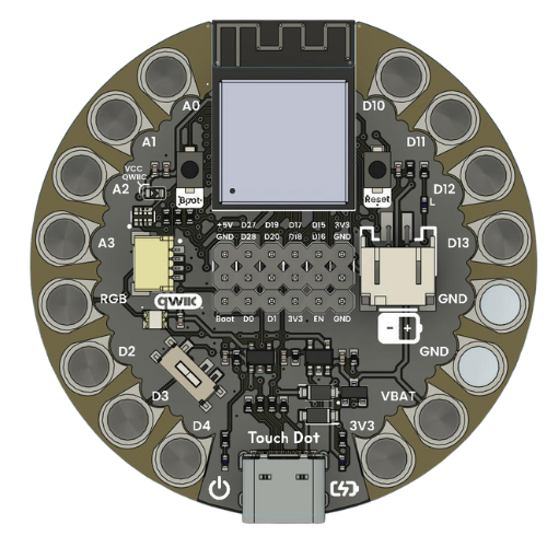
This development board is built around the powerful ESP32-S3 microcontroller, offering a comprehensive range of features for advanced embedded projects. It integrates multiple interfaces including digital I/O, analog inputs, and dedicated communication channels, making it ideal for a variety of applications such as IoT, wearable devices, and rapid prototyping.
Key features include:
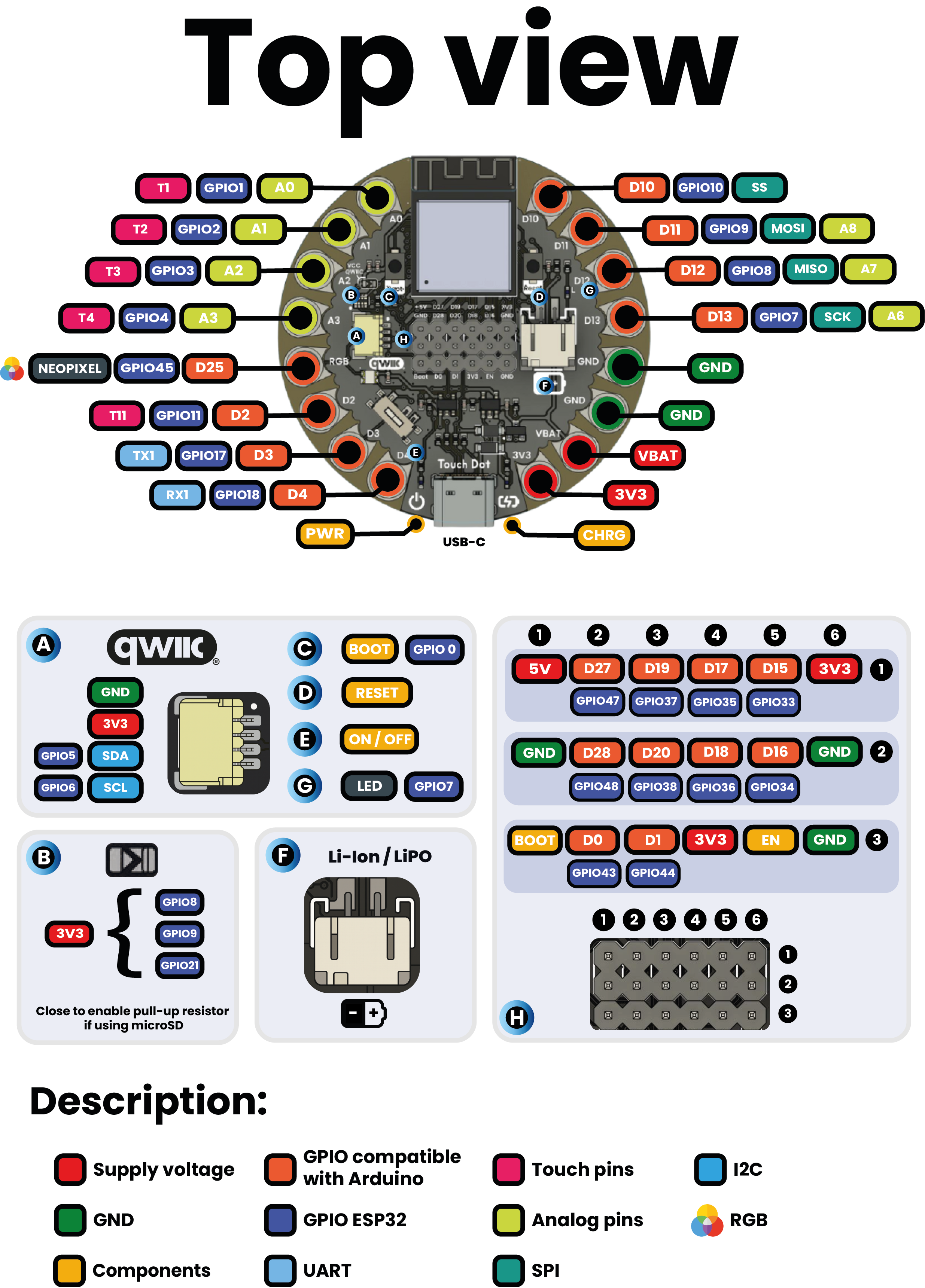
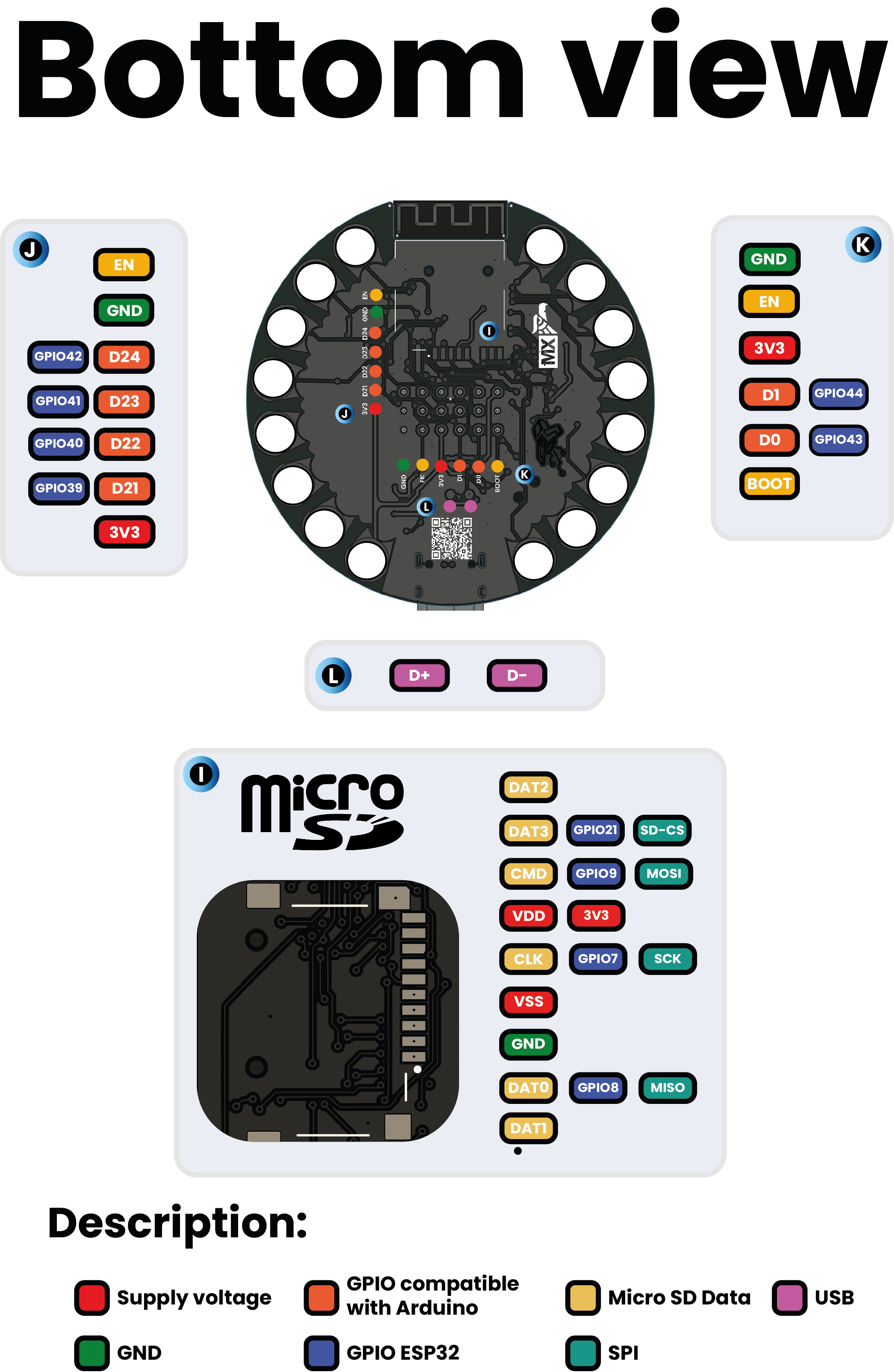
Detailed main pin map for the ESP32-S3 with clearly defined GPIO functions.
QWIIC-compatible JST connector, simplifying sensor and peripheral integrations.
Multiple debugging and programming interfaces including a JTAG test port and a serial programming header.
On-board schematic and pinout images embedded for easy reference via HTML elements.
This versatile design provides users with extensive documentation and hardware accessibility, enabling efficient and effective development workflows.
Pinout Distribution#
Group |
Available Pins |
Suggested Use |
|---|---|---|
GPIO |
D2 to D13 |
Sensors, actuators |
UART |
Tx and Rx |
Serial communication |
TouchPad |
T1 to T11 |
Capacitive sensors for touch detection |
Analog |
A0 to A8 |
12-bit (0–4095) resolution |
SPI |
Optional |
Displays, additional memory |
The following simplified tables present key pinout details.
Main Pin Map ESP32-S3 Touch Dot#
Pin (Arduino/Unit) |
ESP32-S3 GPIO |
Function |
|---|---|---|
D13 (SCK) / D13-SCK/T7 |
GPIO7 |
RTC_GPIO7, TOUCH7 |
3.3V / 3.3V |
3.3V |
Power |
AREF / - |
||
A0 (Analog) / A0/T1 |
GPIO1 |
RTC_GPIO1, TOUCH1 |
A1 (Analog) / A1/T2 |
GPIO2 |
RTC_GPIO2, TOUCH2 |
A2 (Analog) / A2/T3 |
GPIO3 |
RTC_GPIO3, TOUCH3 |
A3 (Analog) / A3/T4 |
GPIO4 |
RTC_GPIO4, TOUCH4 |
A4 (SDA) / A4-SDA/T5 |
GPIO5 |
RTC_GPIO5, TOUCH5 |
A5 (SCL) / A5-SCL/T6 |
GPIO6 |
RTC_GPIO6, TOUCH6 |
5V / 5V |
5V |
Power |
RESET / RST |
EN |
Enable/Disable |
GND / GND |
GND |
Ground |
D0 (RX) / D0-RX |
GPIO44 |
U0RXD |
D1 (TX) / D1-TX |
GPIO43 |
U0TXD |
D2 / D2-T11 |
GPIO11 |
ADC2_CH0 |
D3 / D3-T12 |
GPIO12 |
ADC2_CH1 |
D4 / D4-T13 |
GPIO13 |
ADC2_CH2 |
D5 / D5-T14 |
GPIO14 |
ADC2_CH3 |
D6 |
GPIO15 |
U0RTS |
D7 |
GPIO16 |
U0CTS |
D3 / D5-TX1 |
GPIO17 |
U1TXD |
D4 / D6-RX1 |
GPIO18 |
U1RXD |
D10 (SS) / D10-SS/T10 |
GPIO10 |
TOUCH10 |
D11 (MOSI) / D11-MOSI/T9 |
GPIO9 |
TOUCH9 |
D12 (MISO) / D12-MISO/T8 |
GPIO8 |
TOUCH8 |
QWIIC-Compatible JST Connector#
Pin / JST |
ESP32-S3 GPIO |
Function |
|---|---|---|
1: GND |
GND |
Ground |
2: 3.3V |
3.3V |
3.3V |
3: SDA/MUX (A4) |
GPIO5 |
RTC_GPIO5, TOUCH5 |
4: SCL/MUX (A5) |
GPIO6 |
RTC_GPIO6, TOUCH6 |
JTAG Test Points#
Function (Pin) |
ESP32-S3 GPIO |
Description |
|---|---|---|
MTCK (D21) |
GPIO39 |
MTCK, CLK_OUT3 |
MTDO (D22) |
GPIO40 |
MTDO, CLK_OUT2 |
MTDI (D23) |
GPIO41 |
MTDI, CLK_OUT1 |
MTMS (D24) |
GPIO42 |
MTMS |
GND1 (GND) |
GND |
Ground |
TP_3V3 (3.3V) |
Power |
3.3V |
Serial Programming Header (1x6)#
Pin (JST) |
ESP32-S3 GPIO |
Function |
|---|---|---|
1: GND |
GND |
Ground |
2: EN/RESET |
EN |
Enable/Reset |
3: 3.3V |
3.3V |
3.3V |
4: TX0 (D1) |
GPIO43 |
U0TXD |
5: RX0 (D0) |
GPIO44 |
U0RXD |
6: BOOT (D29) |
GPIO0 |
RTC_GPIO0 |
Expansion Header (2x6)#
Pin / Function |
ESP32-S3 GPIO |
Description |
|---|---|---|
1: 3.3V |
Power |
|
2: GND |
Ground |
|
3: GPIO33 (D15) |
GPIO33 |
SPIIO4, FSPIHD |
4: GPIO34 (D16) |
GPIO34 |
SPIIO5, FSPICS0 |
5: GPIO35 (D17) |
GPIO35 |
SPIIO6, FSPID |
6: GPIO36 (D18) |
GPIO36 |
SPIIO7, FSPICLK |
7: GPIO37 (D19) |
GPIO37 |
SPIDQS, FSPIQ |
8: GPIO38 (D20) |
GPIO38 |
FSPIWP |
9: GPIO47/PDM_DATA (D27) |
GPIO47 |
PDM_DATA |
10: GPIO48/PDM_CLK (D28) |
GPIO48 |
PDM_CLK |
11: 5V |
Power |
|
12: GND |
Ground |