Analog to Digital Conversion#
Learn how to read analog sensor values using the ADC module on the PULSAR C6 development board with the ESP32-C6. This section will cover the basics of analog input and conversion techniques.
ADC Definition#
Analog-to-digital conversion (ADC) is a process that converts analog signals into digital values. The ESP32-C6, equipped with multiple ADC channels, provides flexible options for reading analog voltages and converting them into digital values. Below, you will find the details on how to utilize these pins for ADC operations.
Quantification and Codification of Analog Signals#
Analog signals are continuous signals that can take on any value within a given range. Digital signals, on the other hand, are discrete signals that can only take on specific values. The process of converting an analog signal into a digital signal involves two steps: quantification and codification.
Quantification: This step involves dividing the analog signal into discrete levels. The number of levels determines the resolution of the ADC. For example, a 12-bit ADC can divide the analog signal into 4096 levels.
Codification: This step involves assigning a digital code to each quantization level. The digital code represents the value of the analog signal at that level.
ADC Pin Mapping#
Below is a table showing the distribution of ADC pins on the PULSAR C6 board and their corresponding GPIO pins on the ESP32-C6.
Pin Number |
PULSAR C6 |
ESP32-C6 |
|---|---|---|
1 |
A0/D14 |
GPIO0 |
2 |
A1/D15 |
GPIO1 |
3 |
A2/D16 |
GPIO3 |
4 |
A3/D17 |
GPIO4 |
5 |
A4/D18 |
GPIO22 |
6 |
A5/D19 |
GPIO23 |
7 |
A7 |
GPIO5 |
Class ADC#
The machine.ADC class is used to create ADC objects that can interact with the analog pins.
- class machine.ADC(pin)#
The constructor for the ADC class takes a single argument: the pin number.
Example Definition#
To define and use an ADC object, follow this example:
import machine
adc = machine.ADC(0)  # Initialize ADC on pin A0
#define ADC0 0 // GPIO0 for A0
Reading Values#
To read the analog value converted to a digital format:
adc_value = adc.read()  # Read the ADC value
print(adc_value)  # Print the ADC value
voltage = analogRead(ADC0);
Example Code#
Below is an example that continuously reads from an ADC pin and prints the results:
import machine
import time

# Setup
adc = machine.ADC(machine.Pin(0))  # Initialize pin GPIO0 for ADC

# Continuous reading
while True:
    adc_value = adc.read_u16()        # Read the ADC value
    print(f"ADC Reading: {adc_value:.2f}")  # Print the ADC value
    time.sleep(1)                     # Delay for 1 second
const int adcPin = 0; // GPIO0 (A0)
int adcValue = 0;

void setup() {
  Serial.begin(115200);
  analogReadResolution(12); // Set resolution to 12-bit
  delay(1000);
}

void loop() {
  // Reading ADC value
  adcValue = analogRead(adcPin);
  Serial.println(adcValue);
  delay(500);
}
#include <stdio.h>
#include "esp_log.h"
#include "esp_err.h"
#include "freertos/FreeRTOS.h"
#include "freertos/task.h"
#include "esp_adc/adc_oneshot.h"

static const char *TAG = "ADC_MIN";

void app_main(void)
{
    adc_oneshot_unit_handle_t adc_handle;
    adc_oneshot_unit_init_cfg_t init_cfg = {
        .unit_id = ADC_UNIT_1,
    };
    ESP_ERROR_CHECK(adc_oneshot_new_unit(&init_cfg, &adc_handle));

    adc_oneshot_chan_cfg_t chan_cfg = {
        .bitwidth = ADC_BITWIDTH_DEFAULT,
        .atten = ADC_ATTEN_DB_12,  // <- Usa el recomendado
    };
    ESP_ERROR_CHECK(adc_oneshot_config_channel(adc_handle, ADC_CHANNEL_2, &chan_cfg)); // GPIO2

    int adc_raw;
    while (1) {
        ESP_ERROR_CHECK(adc_oneshot_read(adc_handle, ADC_CHANNEL_2, &adc_raw));
        ESP_LOGI(TAG, "Lectura ADC (GPIO2): %d", adc_raw);
        vTaskDelay(pdMS_TO_TICKS(1000));  // <- Necesitabas incluir FreeRTOS
    }
}
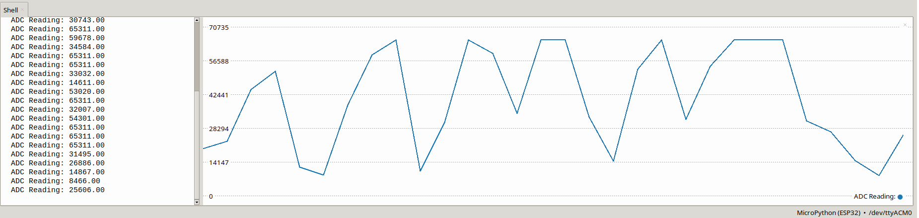
Fig. 13 Example of input ADC0 on the PULSAR C6 board.#