I2C (Inter-Integrated Circuit)#
Discover the I2C communication protocol and learn how to communicate with I2C devices using the PULSAR C6 board. This section will cover I2C bus setup and communication with I2C peripherals.
I2C Overview#
I2C (Inter-Integrated Circuit) is a synchronous, multi-master, multi-slave, packet-switched, single-ended, serial communication bus. It is commonly used to connect low-speed peripherals to processors and microcontrollers. The PULSAR C6 development board features I2C communication capabilities, allowing you to interface with a wide range of I2C devices.
Pinout Details#
Below is the pinout table for the I2C connections on the PULSAR C6, detailing the pin assignments for SDA and SCL.
Pin |
Function |
|---|---|
A4 (SDA)/D18 |
GPIO22 / SDIO_DATA2 |
A5 (SCL)/D19 |
GPIO23 / SDIO_DATA3 |
I2C LP - Inter-Integrated Circuit Low Power#
The I2C LP (Low Power) mode is designed to reduce power consumption during I2C communication. This is particularly useful for battery-powered devices that need to conserve energy. In this mode, the I2C bus operates at lower frequencies and employs various techniques to minimize power usage.
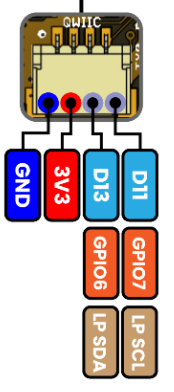
Fig. 14 I2C Pins#
Pin |
Function |
|---|---|
D13 (SDA) |
GPIO6 /LP_SDA |
D11 (SCL) |
GPIO7 / LP_SCL |
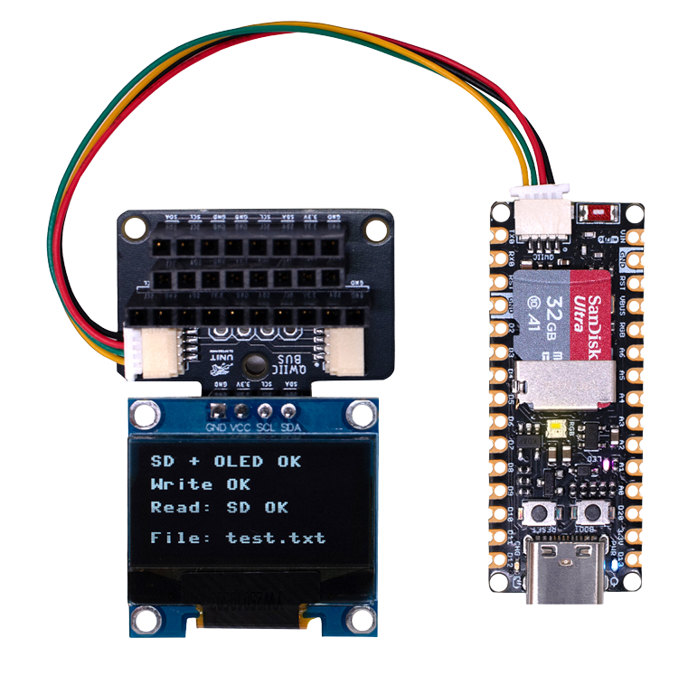
Fig. 15 I2C Pins#
Scanning for I2C Devices#
To scan for I2C devices connected to the bus, you can use the following code snippet:
import machine

i2c = machine.I2C(0, scl=machine.Pin(7), sda=machine.Pin(6))
devices = i2c.scan()

for device in devices:
    print("Device found at address: {}".format(hex(device)))
#include <Wire.h>

void setup() {
  // in setup
  Wire.setSDA(6);
  Wire.setSCL(7);
  Wire.begin();
  Serial.begin(115200); // Start serial communication at 115200 baud rate
  while (!Serial); // Wait for serial port to connect
  Serial.println("\nI2C Scanner");
}

void loop() {
  byte error, address;
  int nDevices;

  Serial.println("Scanning...");

  nDevices = 0;
  for(address = 1; address < 127; address++ ) {
    // The i2c_scanner uses the return value of the Write.endTransmisstion to see if
    // a device did acknowledge to the address.
    Wire.beginTransmission(address);
    error = Wire.endTransmission();

    if (error == 0) {
      Serial.print("I2C device found at address 0x");
      if (address<16)
        Serial.print("0");
      Serial.print(address, HEX);
      Serial.println("  !");

      nDevices++;
    }
    else if (error==4) {
      Serial.print("Unknown error at address 0x");
      if (address<16)
        Serial.print("0");
      Serial.println(address, HEX);
    }
  }
  if (nDevices == 0)
    Serial.println("No I2C devices found\n");
  else
    Serial.println("done\n");

  delay(5000);           // wait 5 seconds for next scan
}
SSD1306 Display#
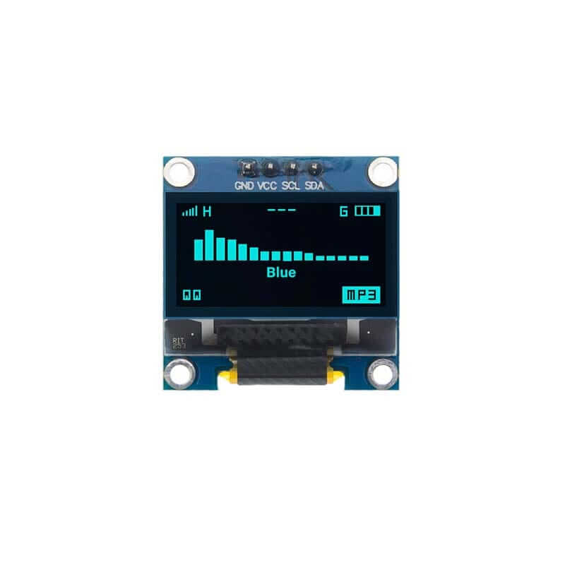
Fig. 16 SSD1306 Display#
The display 128x64 pixel monochrome OLED display equipped with an SSD1306 controller is connected using a JST 1.25mm 4-pin connector. The following table provides the pinout details for the display connection.
Pin |
Connection |
|---|---|
1 |
GND |
2 |
VCC |
3 |
SDA |
4 |
SCL |
Library Support#
The ssd1306.py library for MicroPython on ESP32 & RP2040 is compatible with the SSD1306 display controller.
Installation
Open Thonny.
Copy the library from ssd1306.py.
Paste the library into a new file in Thonny and save it as ssd1306.py on your device.
Microcontroller Configuration
SoftI2C(scl, sda, *, freq=400000, timeout=50000)
Change the following line depending on your microcontroller:
For ESP32:
>>> i2c = machine.SoftI2C(freq=400000, timeout=50000, sda=machine.Pin(21), scl=machine.Pin(22))
For RP2040:
>>> i2c = machine.SoftI2C(freq=400000, timeout=50000, sda=machine.Pin(4), scl=machine.Pin(5))
Example Code
import machine
from ssd1306 import SSD1306_I2C

I2C_SDA_PIN = 6
I2C_SCL_PIN = 7

i2c = machine.SoftI2C(sda=machine.Pin(I2C_SDA_PIN), scl=machine.Pin(I2C_SCL_PIN))

oled = SSD1306_I2C(128, 32, i2c)

oled.fill(1)
oled.show()

oled.fill(0)
oled.show()
oled.text('UNIT', 50, 10)
oled.text('ELECTRONICS', 25, 20)

oled.show()
Replace I2C_SDA_PIN and I2C_SCL_PIN with the appropriate GPIO pins for your setup.
The Adafruit_SSD1306 library for Arduino is compatible with the SSD1306 display controller.
Installation
Open the Arduino IDE.
Navigate to Tools -> Manage Libraries.
Search for
Adafruit_SSD1306and click Install.
Example Code
#include <Wire.h>
#include <Adafruit_GFX.h>
#include <Adafruit_SSD1306.h>

// OLED display TWI (I2C) interface
#define OLED_RESET     -1 // Reset pin # (or -1 if sharing Arduino reset pin)
#define SCREEN_WIDTH   128 // OLED display width, in pixels
#define SCREEN_HEIGHT  64  // OLED display height, in pixels
#define SDA_PIN        4   // SDA pin
#define SCL_PIN        5   // SCL pin

// Declare an instance of the class (specify width and height)
Adafruit_SSD1306 display(SCREEN_WIDTH, SCREEN_HEIGHT, &Wire, OLED_RESET);

void setup() {
  Serial.begin(9600);

  // Initialize I2C
  Wire.setSDA(6);
  Wire.setSCL(7);
  Wire.begin();
  // Start the OLED display
  if(!display.begin(SSD1306_SWITCHCAPVCC, 0x3C)) { // Address 0x3C for 128x64
    Serial.println(F("SSD1306 allocation failed"));
    for(;;); // Don't proceed, loop forever
  }

  // Clear the buffer
  display.clearDisplay();

  // Set text size and color
  display.setTextSize(1);
  display.setTextColor(SSD1306_WHITE);
  display.setCursor(0,0);
  display.println(F("UNIT ELECTRONICS!"));
  display.display();  // Show initial text
  delay(4000);        // Pause for 2 seconds
}

void loop() {
  // Increase a counter
  static int counter = 0;

  // Clear the display buffer
  display.clearDisplay();
  display.setCursor(0, 10); // Position cursor for new text
  display.setTextSize(2);   // Larger text size

  // Display the counter
  display.print(F("Count: "));
  display.println(counter);

  // Refresh the display to show the new count
  display.display();

  // Increment the counter
  counter++;

  // Wait for half a second
  delay(500);
}
#include "ssd1306.h"
#include "driver/i2c.h"
#include "esp_log.h"

#define I2C_MASTER_NUM I2C_NUM_0
#define I2C_MASTER_SDA_IO 6
#define I2C_MASTER_SCL_IO 7
#define I2C_MASTER_FREQ_HZ 100000

static const char *TAG = "MAIN";

void scan_i2c_bus(void) {
   ESP_LOGI(TAG, "Scanning I2C bus...");
   for (uint8_t addr = 1; addr < 127; addr++) {
      i2c_cmd_handle_t cmd = i2c_cmd_link_create();
      i2c_master_start(cmd);
      i2c_master_write_byte(cmd, (addr << 1) | I2C_MASTER_WRITE, true);
      i2c_master_stop(cmd);
      esp_err_t ret = i2c_master_cmd_begin(I2C_MASTER_NUM, cmd, 100 / portTICK_PERIOD_MS);
      i2c_cmd_link_delete(cmd);
      if (ret == ESP_OK) {
        ESP_LOGI(TAG, "Found device at 0x%02X", addr);
      }
   }
   ESP_LOGI(TAG, "Scan complete.");
}

void app_main(void) {
   i2c_config_t conf = {
      .mode = I2C_MODE_MASTER,
      .sda_io_num = I2C_MASTER_SDA_IO,
      .scl_io_num = I2C_MASTER_SCL_IO,
      .sda_pullup_en = GPIO_PULLUP_ENABLE,
      .scl_pullup_en = GPIO_PULLUP_ENABLE,
      .master.clk_speed = I2C_MASTER_FREQ_HZ,
   };

   i2c_param_config(I2C_MASTER_NUM, &conf);
   i2c_driver_install(I2C_MASTER_NUM, conf.mode, 0, 0, 0);

   scan_i2c_bus(); // Optional

   ssd1306_init(I2C_MASTER_NUM);
   ssd1306_clear(I2C_MASTER_NUM);
   ssd1306_draw_text(I2C_MASTER_NUM, 0, "ESP32-C6 ");
   ssd1306_draw_text(I2C_MASTER_NUM, 2, "I2C Scan + OLED");
   ssd1306_draw_text(I2C_MASTER_NUM, 4, "Monosaurio");
}
Application Example#
Emotionally – Reacting Face with MicroPython on Pulsar C6#
Bring your board to life with emotions! This project demonstrates how to use the SSD1306 OLED display and MPU6050 IMU sensor with the PULSAR C6 board to create an interactive, emotionally-reacting face.
Project Overview
Emotionally is a cute and expressive project that reacts to how you move it: shake it hard and it gets angry, leave it alone and it gets sleepy. It’s the perfect example of using sensors and displays to give character to embedded systems.
Hardware Components
PULSAR C6 development board
SSD1306 OLED display (128x64)
MPU6050 IMU sensor
I2C Qwiic connector
Emotions Logic
Happy: Gentle movement
Surprised: Moderate shaking
Angry: Harsh motion
Sleepy: Still (with ZzZ animation)
Software Setup
Flash MicroPython to the Pulsar C6
Upload
main.pyandmpu6050.pyusing mpremote or ThonnyPower on the board — the face will appear on the screen
Move the board and watch the expression change in real-time!
This project is ideal for STEM education, IoT toys, wearables, and user-interface experiments.
Fig. 17 Emotionally – Reacting Face Demo#
For complete code, schematics, and detailed instructions, visit the Hackster.io project page.