PULSAR H2 Development Board#
Introduction#
This guide will help you get started with the PULSAR H2 development board. The PULSAR H2 is a development board based on the ESP32H2 microcontroller. It is designed for prototyping and developing IoT applications. The board features a variety of interfaces, including GPIO, I2C, SPI, UART, and more. It also has built-in support for Zigbee, Thread (802.15.4), and Bluetooth connectivity.
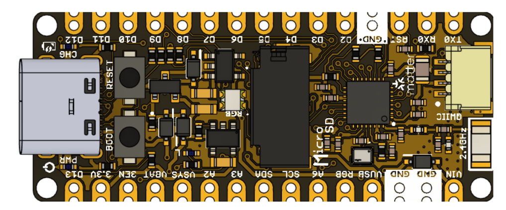
Fig. 2 PULSAR H2 Development Board#
Features#
CPU#
Espressif ESP32-H2FH4S
Single-core 32-bit RISC-V processor
Up to 96 MHz operating frequency
Four-stage pipeline
Internal Memory#
320 KB of internal SRAM
128 KB of ROM (for boot and system functions)
4 MB of integrated SPI Flash (in the ESP32-H2FH4 module)
4 KB LP Memory
16 KB cache
Wireless Connectivity#
Bluetooth® 5.0 LE, supports LE 2M, LE Coded PHY, Extended Advertising, and Advertising Extensions
IEEE 802.15.4 for Zigbee and Thread, with support for Matter over Thread
Peripheral Interfaces#
19 programmable GPIOs (including GPIO8, GPIO9, and GPIO25 as strapping pins)
12-bit SAR ADC (up to 5 channels)
Temperature sensor
SPI, UART, I²C, I²S, PWM, RMT
USB 2.0 Full-Speed (with integrated Serial/JTAG controller and PHY)
General-purpose SPI, UART (×2), and I²C (×2) interfaces
RMT with up to 2 transmit channels and 2 receive channels
LED PWM controller (up to 6 channels)
Motor Control PWM (MCPWM)
Pulse Count Controller
General DMA controller (3 TX channels, 3 RX channels)
Parallel I/O (PARLIO) controller
SoC Event Task Matrix (ETM)
Two TWAI® Controllers (compatible with ISO 11898-1 / CAN 2.0)
Two 54-bit general-purpose timers
52-bit system timer
Three watchdog timers
SDIO, JTAG, GPIO
Built-in Security#
Secure Boot – Ensures firmware integrity during startup
Flash Encryption – Provides secure memory encryption and decryption
4096-bit OTP (One-Time Programmable memory), with up to 1792 bits available for user data
Cryptographic Hardware Acceleration#
AES-128/256 (FIPS PUB 197) – Supports ECB, CBC, CFB, OFB, and CTR modes (FIPS PUB 800-38A)
SHA Accelerator (FIPS PUB 180-4)
RSA Accelerator
ECC Accelerator
ECDSA (Elliptic Curve Digital Signature Algorithm)
HMAC (Hash-based Message Authentication Code)
Digital Signature Engine
Access Permission Management (APM)
Random Number Generator (RNG)
Power Glitch Detector
Power Management and Operating Voltage#
I/O Operating Voltage: 3.3 V
Ultra-Low Power Consumption – Designed for energy-efficient applications requiring extended battery life
Fine-resolution power control through adjustable clock frequency, duty cycle, RF operating modes, and individual power control of internal components
Four Power Modes optimized for different operation scenarios:
Active, Modem-sleep, Light-sleep, and Deep-sleep
Power Consumption in Deep-sleep Mode: 7 µA
Independent RTC (Real-Time Clock) for data and event retention during Deep-sleep mode
LP (Low-Power) memory remains powered on in Deep-sleep mode
Antenna#
Integrated PCB antenna (no external antenna required)
Storage#
Integrated microSD card slot via SPI for data logging, multimedia storage, and firmware updates
Connected to GPIO0, GPIO4, GPIO5, and GPIO25
Power Management#
Vin: Up to 6V via pin header
USB-C powered (5V input)
VUSB Output: Available
3.3V AP2112K 3.3V LDO Regulator (max input 6V): 350 mA nominal current, up to 600 mA peak with thermal protection
Supports LiPo battery charging with an onboard power management circuit. Charging current: 200 mA
Interfaces and Connectors#
1 × I2C JST-SH (1.0 mm pitch): Qwiic-compatible connector wired to GPIO12 and GPIO22 for Low-Power I2C
1 × microSD Card Holder
1 × Auxiliary Battery Connector (optional): Supports both 2.0 mm and 1.25 mm pitch options
1 × USB Type-C Connector
2 × 15-pin Header Connectors: With castellated holes for easy surface mounting
Communication and Connectivity#
USB-C connector for programming and power
Reset button and Flash/Boot button for manually entering flash mode
LED Indicators#
Green or Red PWR LED (0603) – Power indication
Orange CHG LED (0603) – LiPo charging status
Pink BLINK LED (0603, GPIO4) – User-programmable
WS2812 RGB LED (2020) – Fully addressable for status or visual feedback connected to GPIO8
Software Support#
Arduino IDE (official Uelectronics-ESP32 Arduino Package)
ESP-IDF for advanced native development
MicroPython and CircuitPython support
PlatformIO / VS Code for professional development
Applications#
Smart Home (Matter, Thread)
Home and Industrial Automation (including CAN Bus and low-power systems)
IoT Prototyping and Embedded Development
Multi-radio Devices and Mesh Communication
Robotics and Sensor Networks