ESP32-H2 MicroPython Installation#
This section provides comprehensive instructions for installing and using MicroPython on the PULSAR H2 board with ESP32-H2 microcontroller.
ESP32-H2 MicroPython v1.0 - Complete Binary#
Download and Installation Files#
The firmware is available in the following location:
- ESP32H2_MicroPython_v1.0_Complete.bin (1,557,600 bytes)
Complete binary ready to flash from 0x0000
Includes: Bootloader + Partition Table + MicroPython
Download:
ESP32H2 MicroPython v1.0
- flash_esp32h2.sh
Automatic script to flash ESP32-H2
Automatic port detection
Connection verification
- compile_py_to_mpy.sh
Python to .mpy bytecode compiler
Size and speed optimization
Installation Methods#
Web-Based Flashing (Recommended for Beginners)#
Using ESPTool-JS Web Flasher:
Open Web Flasher: Navigate to
Connect Device: Connect your PULSAR H2 via USB-C
Device Detection: Click “Connect” and select your ESP32-H2 device
Configure Flashing Parameters:
Flash Address:
0x00000Choose File: Select
ESP32H2_MicroPython_v1.0_Complete.binChip: ESP32-H2
Baudrate: 115200
Flash Mode: DIO
Flash Size: 4MB
Reset Method: Hard Reset
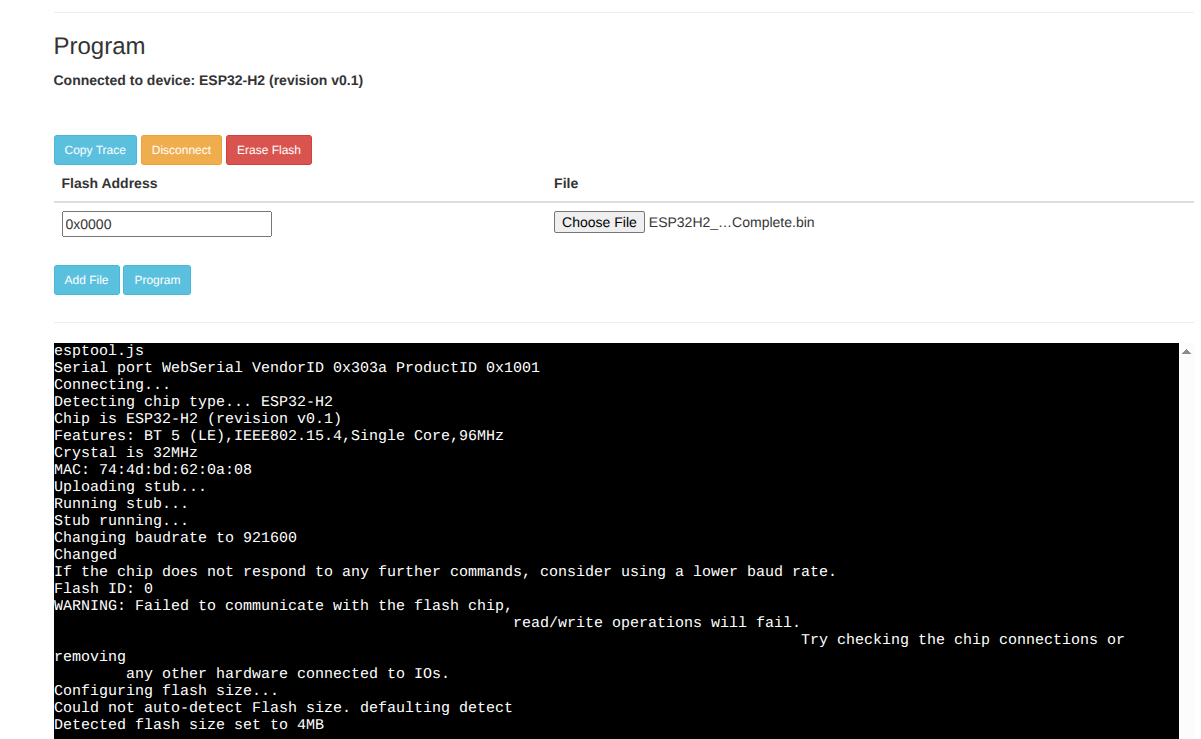
Fig. 11 ESPTool-JS Configuration Example#
Important
Flash Erase Recommended
For optimal MicroPython firmware performance and to prevent potential issues:
Click “Erase” button in ESPTool-JS before flashing the firmware
Wait for erase completion (takes ~30 seconds)
Then flash the MicroPython binary
This process clears any existing firmware or data that might interfere with MicroPython execution, ensuring a clean installation and preventing boot loops or unexpected behavior.
Start Flashing: Click “Program” button
Wait for completion: Process takes approximately 2-3 minutes
Manual Flashing with ESPTool#
# Install esptool if not already installed
pip install esptool

# Flash the complete binary
python3 -m esptool --chip esp32h2 --port /dev/ttyACM0 --baud 460800 \
    --before default_reset --after hard_reset write_flash \
    --flash_mode dio --flash_freq 48m --flash_size 4MB \
    0x0 ESP32H2_MicroPython_v1.0_Complete.bin
Connecting to MicroPython REPL#
After successful flashing, connect to the MicroPython REPL:
1. Open Thonny IDE
2. Go to Tools > Options > Interpreter
3. Select "MicroPython (ESP32)"
4. Choose correct COM port
5. Click OK and connect
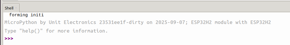
Fig. 12 Thonny IDE Configuration Example#
# Using PuTTY or built-in serial terminal
# Port: COM3 (check Device Manager)
# Baud Rate: 115200
# Using picocom
picocom -b 115200 /dev/ttyACM0

# Using screen
screen /dev/ttyACM0 115200

# Using miniterm
python3 -m serial.tools.miniterm /dev/ttyACM0 115200
Enabled Features and Capabilities#
GPIO (General Purpose Input/Output)#
Available pins: GPIO 0-27 (28 pins total)
Recommended pins for LED: 4, 5, 6, 7, 10, 11, 22, 23, 24, 25
Configuration: Input/Output, Pull-up/Pull-down
ADC (Analog-to-Digital Converter)#
Channels: 5 available channels
ADC pins: GPIO1, GPIO2, GPIO3, GPIO4, GPIO5
Resolution: 12 bits
Voltage Range: 0-3.3V
Communication Protocols#
UART: REPL enabled via USB-Serial/JTAG
I2C: Hardware I2C available on GPIO12 (SDA) and GPIO22 (SCL)
SPI: Hardware SPI available
Bluetooth LE: Fully functional Bluetooth 5.0 Low Energy
IEEE 802.15.4: For Thread/Zigbee protocols
Memory Configuration#
Flash: 4MB configured
RAM: ~256KB available for applications
- Partitions:
NVS: 24KB
PHY: 4KB
App: 1984KB
VFS: 2MB
Test Code Examples#
Basic LED Blink#
import machine
import time

# Use GPIO4 which is connected to the built-in LED
led = machine.Pin(4, machine.Pin.OUT)

while True:
    led.on()
    time.sleep(1)
    led.off()
    time.sleep(1)
ADC Reading#
import machine

# ADC on GPIO1
adc = machine.ADC(machine.Pin(1))
adc.atten(machine.ADC.ATTN_11DB)  # 0-3.3V range

# Read value
value = adc.read()
voltage = value * 3.3 / 4095
print(f"ADC Value: {value}, Voltage: {voltage:.2f}V")
I2C Communication#
import machine

# Initialize I2C on PULSAR H2 pins
i2c = machine.I2C(0, scl=machine.Pin(22), sda=machine.Pin(12), freq=100000)

# Scan for I2C devices
devices = i2c.scan()
print(f"I2C devices found: {[hex(device) for device in devices]}")
SPI Communication#
import machine

# Initialize SPI for microSD (PULSAR H2 configuration)
spi = machine.SPI(1,
                  sck=machine.Pin(5),   # Clock
                  mosi=machine.Pin(4),  # Data Out
                  miso=machine.Pin(0))  # Data In

cs = machine.Pin(25, machine.Pin.OUT)  # Chip Select
cs.value(1)  # Deselect initially
Bluetooth LE Example#
import bluetooth

# Initialize Bluetooth LE
ble = bluetooth.BLE()
ble.active(True)

# Start advertising
ble.gap_advertise(100, b'\x02\x01\x02\x0b\tPULSAR_H2')
print("Bluetooth LE advertising started")
Performance Optimization#
Compile to .mpy (Optimized Bytecode)#
For better performance and reduced memory usage:
# Install mpy-cross compiler
pip install mpy-cross

# Compile single file
./compile_py_to_mpy.sh my_script.py

# Compile with optimization level 2
./compile_py_to_mpy.sh -O2 my_script.py

# Compile entire directory
./compile_py_to_mpy.sh src/
Technical Specifications#
ESP32-H2 Chip Features#
Architecture: RISC-V single-core 96MHz
WiFi: Not available (by chip design)
Bluetooth: Full LE 5.0 support
IEEE 802.15.4: Thread/Zigbee/Matter protocols
Security: Crypto accelerator, Secure boot
Power Management: Ultra-low power modes
Firmware Versions#
MicroPython: v1.23.0+ (custom build for ESP32-H2)
ESP-IDF: 5.4.1
Compiler: GCC 14.2.0
Build Date: September 7, 2025
Version: 1.0 (First Official Release)
Library Installation (No Wi-Fi Alternative)#
Since ESP32-H2 doesn’t support Wi-Fi, use these methods for library installation:
Manual Library Installation#
# Example: Manual library installation
# Download these libraries manually and copy to ESP32-H2:
# - max1704x.py from UNIT-Electronics/MAX1704X_lib
# - ssd1306.py for OLED displays
# - sdcard.py for SD card support

# After copying files manually via USB:
import max1704x
import ssd1306
import sdcard
Pre-compiled Libraries#
Download on computer: Use a computer with internet access
Transfer via USB: Copy .py or .mpy files to ESP32-H2
Use Thonny file manager: Drag and drop files to device
Available Libraries#
OLED Support: SSD1306 driver for I2C displays
SD Card: File system support for microSD
Sensors: I2C/SPI sensor libraries
Communication: Bluetooth LE utilities
Hardware: GPIO, ADC, PWM libraries
Troubleshooting#
Common Issues#
- 1. “Invalid pin” GPIO Error
Fixed in MicroPython v1.0
All GPIO 0-27 now work correctly
2. Connection Error During Flashing
# Verify connection
./flash_esp32h2.sh --verify

# Try specific port
./flash_esp32h2.sh /dev/ttyACM0

# Check if device is in download mode
esptool.py --port /dev/ttyACM0 chip_id
3. Serial Port Permissions (Linux)
# Add user to dialout group
sudo usermod -a -G dialout $USER
# Log out and back in after this change
- 4. Thonny Connection Issues
Ensure correct interpreter: “MicroPython (ESP32)”
Check COM port in device manager
Try different baud rates: 115200, 9600
- 5. Memory Issues
Use .mpy compiled files
Implement garbage collection:
import gc; gc.collect()Monitor memory:
import micropython; micropython.mem_info()
Next Steps and Project Ideas#
Beginner Projects#
LED Control: RGB LED strips, status indicators
Sensor Reading: Temperature, humidity, light sensors
Display Output: OLED displays, status screens
Data Logging: SD card storage, sensor data
Intermediate Projects#
Bluetooth LE Communication: Mobile app integration
I2C Sensor Networks: Multiple sensor reading
IoT Data Collection: Local sensor hub
Real-time Monitoring: Battery, environmental data
Advanced Projects#
IEEE 802.15.4 Networks: Thread/Zigbee implementation
Matter Protocol: Smart home device integration
Mesh Networks: Multi-device communication
Security Applications: Encrypted data transmission
Resources and Documentation#
MicroPython Official Docs: https://docs.micropython.org/
ESP32-H2 Datasheet: Available in project documentation
PULSAR H2 Hardware Guide: See hardware documentation section
Community Support: ESP32 MicroPython forums and GitHub
—
Created by: ESP32-H2 MicroPython Development Team Documentation Version: 1.0 Last Updated: October 2025