SPI (Serial Peripheral Interface)#
SPI Overview#
SPI (Serial Peripheral Interface) is a synchronous, full-duplex, master-slave communication bus. It is commonly used to connect microcontrollers to peripherals such as sensors, displays, and memory devices. The PULSAR H2 development board features SPI communication capabilities, allowing you to interface with a wide range of SPI devices including microSD cards.
SPI Pin Configuration#
The ESP32-H2 PULSAR H2 board has the following SPI pin configuration:
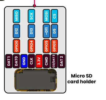
Fig. 19 PULSAR H2 Internal SPI Configuration#
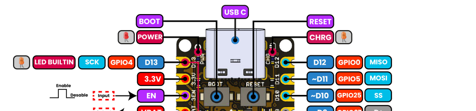
Fig. 20 External SPI Device Connection#
MicroSD Card SPI Interface#
Warning
Ensure that the Micro SD contains data. We recommend saving multiple files beforehand to facilitate testing. Format the Micro SD card to FAT32 before using it with the ESP32-H2.
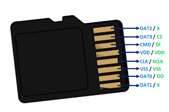
Fig. 21 Micro SD Card Pinout#
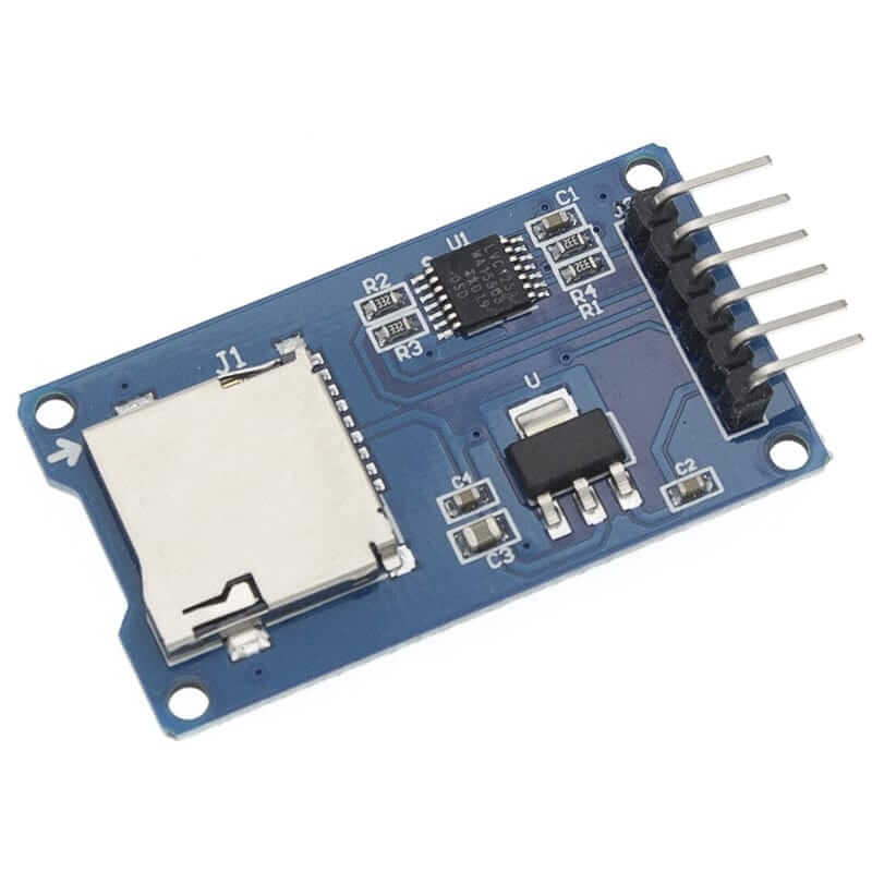
Fig. 22 Micro SD Card external reader#
The conections are as follows:
This table illustrates the connections between the SD card and the GPIO pins on the ESP32-H2 (PULSAR H2)
SD Card Pin |
Function |
ESP32-H2 GPIO |
PULSAR H2 Pin |
|---|---|---|---|
1 |
D2 (Not Connected) |
N/C |
— |
2 |
D3/CS (Chip Select) |
GPIO11 |
D10/SS |
3 |
CMD/MOSI |
GPIO5 |
D11/MOSI |
4 |
VDD (3.3V) |
3.3V |
3.3V |
5 |
CLK/SCK |
GPIO4 |
D13/SCK |
6 |
VSS (GND) |
GND |
GND |
7 |
D0/MISO |
GPIO0 |
D12/MISO |
8 |
D1 (Not Connected) |
N/C |
— |
SPI Pin Mapping Summary#
SPI Function |
ESP32-H2 GPIO |
PULSAR H2 Pin |
Description |
|---|---|---|---|
MOSI (Master Out) |
GPIO5 |
D11/MOSI |
Data output from master |
MISO (Master In) |
GPIO0 |
D12/MISO |
Data input to master |
SCK (Clock) |
GPIO4 |
D13/SCK |
Serial clock signal |
CS (Chip Select) |
GPIO11 |
D10/SS |
Device selection signal |
Note
MicroSD Connection Notes:
The microSD card is connected via SPI interface using 4 wires (MOSI, MISO, SCK, CS)
CS (Chip Select) is connected to GPIO11 (D10/SS pin)
MOSI is connected to GPIO5 (D11/MOSI pin)
MISO is connected to GPIO0 (D12/MISO pin)
SCK is connected to GPIO4 (D13/SCK pin)
D2 and D1 pins of the SD card are not used in SPI mode
Make sure the SD card is formatted as FAT32 before use
The SD card operates at 3.3V - no level shifters needed
from machine import Pin, SPI
import os
import sdcard
import time

# --- Custom pin configuration ---
MOSI_PIN = 5
MISO_PIN = 0
SCK_PIN  = 4
CS_PIN   = 11

# --- Initialize SPI with custom pins ---
spi = SPI(
    1,                   # Bus SPI(1) = HSPI (can use remapped pins)
    baudrate=5_000_000,  # 5 MHz is more stable with long cables or sensitive SDs
    polarity=0,
    phase=0,
    sck=Pin(SCK_PIN),
    mosi=Pin(MOSI_PIN),
    miso=Pin(MISO_PIN)
)

# --- Chip Select pin ---
cs = Pin(CS_PIN, Pin.OUT)

# --- Initialize SD card ---
try:
    sd = sdcard.SDCard(spi, cs)
    vfs = os.VfsFat(sd)
    os.mount(vfs, "/sd")
    print("microSD mounted successfully at /sd\n")

    # --- List contents ---
    print("Contents of /sd:")
    for fname in os.listdir("/sd"):
        print(" -", fname)

    # --- Read/write test ---
    test_path = "/sd/test.txt"
    with open(test_path, "w") as f:
        f.write("Hello from ESP32 with custom SPI pins!\n")
    print(f"\nFile created: {test_path}")

    with open(test_path, "r") as f:
        print("\nFile contents:")
        print(f.read())

except Exception as e:
    print("Error initializing SD card:", e)

# --- Infinite loop ---
while True:
    time.sleep(1)
#include <SPI.h>
#include <SD.h>

// Pines SPI para microSD
#define MOSI_PIN 5
#define MISO_PIN 0
#define SCK_PIN 4
#define CS_PIN 11

File myFile;

void setup() {
  Serial.begin(115200);
  while (!Serial) ; // Wait for serial port to be ready

  SPI.begin(SCK_PIN, MISO_PIN, MOSI_PIN, CS_PIN);

  Serial.println("Initializing SD card...");

  if (!SD.begin(CS_PIN)) {
    Serial.println("Error initializing SD card.");
    return;
  }

  Serial.println("SD card initialized successfully.");

  // List files
  Serial.println("Files on SD card:");
  listDir(SD, "/", 0);

  // Create and write to file
  myFile = SD.open("/test.txt", FILE_WRITE);
  if (myFile) {
    myFile.println("Hello, Arduino on SD!");
    myFile.println("This is a write test.");
    myFile.close();
    Serial.println("File written successfully.");
  } else {
    Serial.println("Error opening test.txt for writing.");
  }

  // Read the file
  myFile = SD.open("/test.txt");
  if (myFile) {
    Serial.println("\nFile contents:");
    while (myFile.available()) {
      Serial.write(myFile.read());
    }
    myFile.close();
  } else {
    Serial.println("Error opening test.txt for reading.");
  }

  // List files again
  Serial.println("\nFiles on SD card after writing:");
  listDir(SD, "/", 0);
}

void loop() {
  // Nothing in the loop
}

// Function to list files and folders
void listDir(fs::FS &fs, const char * dirname, uint8_t levels) {
  File root = fs.open(dirname);
  if (!root) {
    Serial.println("Error opening directory");
    return;
  }
  if (!root.isDirectory()) {
    Serial.println("Not a directory");
    return;
  }

  File file = root.openNextFile();
  while (file) {
    Serial.print("  ");
    Serial.print(file.name());
    if (file.isDirectory()) {
      Serial.println("/");
      if (levels) {
        listDir(fs, file.name(), levels - 1);
      }
    } else {
      Serial.print("\t\t");
      Serial.println(file.size());
    }
    file = root.openNextFile();
  }
}
#include <stdio.h>
#include <string.h>
#include <sys/stat.h>
#include <sys/unistd.h>
#include "esp_log.h"
#include "esp_vfs_fat.h"
#include "sdmmc_cmd.h"
#include "driver/gpio.h"

#define TAG "SD_OPS"
#define MOUNT_POINT "/sdcard"
#define FILE_PREFIX MOUNT_POINT"/data_"
#define MAX_FILES 20

#define PIN_NUM_MISO  0
#define PIN_NUM_MOSI  5
#define PIN_NUM_CLK   4
#define PIN_NUM_CS    11
#define BTN_PIN       GPIO_NUM_9

FILE* safe_fopen(const char* path, const char* mode, int tries) {
    FILE* f = NULL;
    for (int i = 0; i < tries; ++i) {
        f = fopen(path, mode);
        if (f) return f;
        vTaskDelay(50 / portTICK_PERIOD_MS);
    }
    return NULL;
}

esp_err_t mount_sdcard(sdmmc_card_t **card_out) {
    sdmmc_host_t host = SDSPI_HOST_DEFAULT();
    host.max_freq_khz = 4000;

    spi_bus_config_t bus_cfg = {
        .mosi_io_num = PIN_NUM_MOSI,
        .miso_io_num = PIN_NUM_MISO,
        .sclk_io_num = PIN_NUM_CLK,
        .quadwp_io_num = -1,
        .quadhd_io_num = -1,
        .max_transfer_sz = 4000,
    };

    gpio_set_pull_mode(PIN_NUM_MISO, GPIO_PULLUP_ONLY);
    gpio_set_pull_mode(PIN_NUM_MOSI, GPIO_PULLUP_ONLY);
    gpio_set_pull_mode(PIN_NUM_CLK, GPIO_PULLUP_ONLY);
    gpio_set_pull_mode(PIN_NUM_CS, GPIO_PULLUP_ONLY);

    esp_err_t ret = spi_bus_initialize(host.slot, &bus_cfg, SDSPI_DEFAULT_DMA);
    if (ret == ESP_ERR_INVALID_STATE) {
        ESP_LOGW(TAG, "SPI bus already initialized, attempting to free and reinitialize.");
        spi_bus_free(host.slot);  // Libera el bus anterior
        ret = spi_bus_initialize(host.slot, &bus_cfg, SDSPI_DEFAULT_DMA);
    }

    if (ret != ESP_OK) {
        ESP_LOGE(TAG, "SPI bus init failed: %s", esp_err_to_name(ret));
        return ret;
    }

    sdspi_device_config_t slot_config = SDSPI_DEVICE_CONFIG_DEFAULT();
    slot_config.gpio_cs = PIN_NUM_CS;
    slot_config.host_id = host.slot;

    esp_vfs_fat_sdmmc_mount_config_t mount_config = {
        .format_if_mount_failed = false,
        .max_files = 5,
        .allocation_unit_size = 16 * 1024
    };

    sdmmc_card_t *card;
    ret = esp_vfs_fat_sdspi_mount(MOUNT_POINT, &host, &slot_config, &mount_config, &card);
    if (ret != ESP_OK) {
        ESP_LOGE(TAG, "SD mount failed: %s", esp_err_to_name(ret));
        spi_bus_free(host.slot);  // Importante: liberar SPI si falla montaje
        return ret;
    }

    *card_out = card;
    sdmmc_card_print_info(stdout, card);
    return ESP_OK;
}


void write_files() {
    for (int i = 0; i < MAX_FILES; i++) {
        char path[64];
        snprintf(path, sizeof(path), FILE_PREFIX"%d.txt", i);
        FILE *f = safe_fopen(path, "w", 5);
        if (f) {
            fprintf(f, "This is file number %d\n", i);
            fflush(f);
            fclose(f);
            ESP_LOGI(TAG, "Wrote %s", path);
        } else {
            ESP_LOGE(TAG, "Failed to write %s", path);
        }
        vTaskDelay(10 / portTICK_PERIOD_MS);
    }
}

void read_files() {
    for (int i = 0; i < MAX_FILES; i++) {
        char path[64], buffer[128];
        snprintf(path, sizeof(path), FILE_PREFIX"%d.txt", i);
        FILE *f = safe_fopen(path, "r", 5);
        if (f) {
            if (fgets(buffer, sizeof(buffer), f)) {
                ESP_LOGI(TAG, "[%d] %s", i, buffer);
            } else {
                ESP_LOGW(TAG, "File %s is empty or unreadable.", path);
            }
            fclose(f);
        } else {
            ESP_LOGE(TAG, "Failed to read %s", path);
        }
        vTaskDelay(10 / portTICK_PERIOD_MS);
    }
}

void wait_for_button_press() {
    ESP_LOGI(TAG, "Waiting for button press (GPIO9) to retry...");
    while (gpio_get_level(BTN_PIN) == 1) {
        vTaskDelay(100 / portTICK_PERIOD_MS);
    }
    while (gpio_get_level(BTN_PIN) == 0) {
        vTaskDelay(100 / portTICK_PERIOD_MS);
    }
    vTaskDelay(200 / portTICK_PERIOD_MS);
}

void app_main(void)
{
    gpio_config_t io_conf = {
        .pin_bit_mask = (1ULL << BTN_PIN),
        .mode = GPIO_MODE_INPUT,
        .pull_up_en = GPIO_PULLUP_ENABLE,
        .pull_down_en = GPIO_PULLDOWN_DISABLE,
        .intr_type = GPIO_INTR_DISABLE
    };
    gpio_config(&io_conf);

    while (1) {
        sdmmc_card_t *card;
        ESP_LOGI(TAG, "Mounting SD card...");

        if (mount_sdcard(&card) == ESP_OK) {
            ESP_LOGI(TAG, "SD card mounted. Starting file operations.");
            write_files();
            read_files();
            esp_vfs_fat_sdcard_unmount(MOUNT_POINT, card);
            sdmmc_host_t host = SDSPI_HOST_DEFAULT();
            spi_bus_free(host.slot);
            ESP_LOGI(TAG, "SD card unmounted and SPI bus freed.");
        } else {
            ESP_LOGW(TAG, "Operation aborted due to mount failure.");
        }

        wait_for_button_press();
    }
}
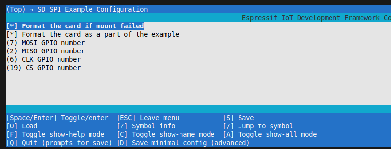
Fig. 23 ESP-IDF Menuconfig SD SPI Configuration#
General SPI Device Connection#
Besides microSD cards, you can connect various SPI devices to the PULSAR H2:
Common SPI Devices#
Device Type |
Example Models |
Applications |
|---|---|---|
Displays |
ST7735, ILI9341, SSD1306 |
Status displays, GUI interfaces |
Sensors |
BME280, MPU6050, MAX31855 |
Environmental monitoring, IMU |
Memory |
W25Q32, AT25DF641, microSD |
Data storage, logging |
ADC/DAC |
MCP3008, MCP4725 |
Analog signal processing |
RF Modules |
nRF24L01, LoRa modules |
Wireless communication |
SPI Configuration Tips#
# General SPI device connection example
from machine import Pin, SPI

# Initialize SPI bus with standard pins
spi = SPI(1,
          sck=Pin(4),   # Clock
          mosi=Pin(5),  # Master Out, Slave In
          miso=Pin(0),  # Master In, Slave Out
          baudrate=1000000)  # 1MHz for most devices

# Individual chip select pins for multiple devices
cs_display = Pin(11, Pin.OUT)
cs_sensor = Pin(10, Pin.OUT)
cs_memory = Pin(9, Pin.OUT)

# Device selection example
cs_display.value(0)  # Select display
spi.write(b'display_data')
cs_display.value(1)  # Deselect display
Troubleshooting SPI#
Common Issues:
Device not responding: Check wiring and power supply
Data corruption: Reduce SPI clock frequency
Multiple device conflicts: Ensure proper CS management
Signal integrity: Use short wires, add pull-up resistors if needed
Best Practices:
Use appropriate SPI clock frequencies for each device
Implement proper chip select (CS) timing
Add decoupling capacitors near SPI devices
Keep wire lengths short for high-frequency signals