I2C (Inter-Integrated Circuit)#
Discover the I2C communication protocol and learn how to communicate with I2C devices using the PULSAR H2 board. This section will cover I2C bus setup and communication with I2C peripherals.
I2C Overview#
I2C (Inter-Integrated Circuit) is a synchronous, multi-master, multi-slave, packet-switched, single-ended, serial communication bus. It is commonly used to connect low-speed peripherals to processors and microcontrollers.
The PULSAR H2 development board, powered by the ESP32-H2, features advanced I2C communication capabilities with two I2C controllers that support:
Standard mode (100 kbit/s) and Fast mode (400 kbit/s)
Master and slave modes
7-bit and 10-bit addressing
Dual address mode support
Programmable digital noise filtering
SCL clock stretching in slave mode
Pinout Details#
Below is the pinout table for the I2C connections on the PULSAR H2, detailing the pin assignments for SDA and SCL.
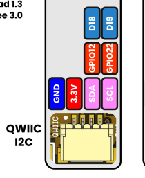
Fig. 16 PULSAR H2 Pinout#
Pin |
Function |
|---|---|
A4 (SDA)/D18 |
GPIO12 / I2C SDA |
A5 (SCL)/D19 |
GPIO22 / I2C SCL |
I2C Features on ESP32-H2#
The ESP32-H2 is designed as an ultra-low-power microcontroller, making it inherently energy-efficient for I2C communication. Key features include:
Ultra-low power consumption: The ESP32-H2 is optimized for battery-powered applications
Two I2C controllers: Support for multiple I2C buses
Flexible GPIO assignment: I2C pins can be assigned to any available GPIO
Standard and Fast modes: Support for 100 kbit/s (Standard) and 400 kbit/s (Fast mode)
Master and slave modes: Can operate as either I2C master or slave device
Note
Unlike other ESP32 variants, the ESP32-H2 doesn’t have a separate “LP I2C” mode because the entire chip is designed for low power operation.
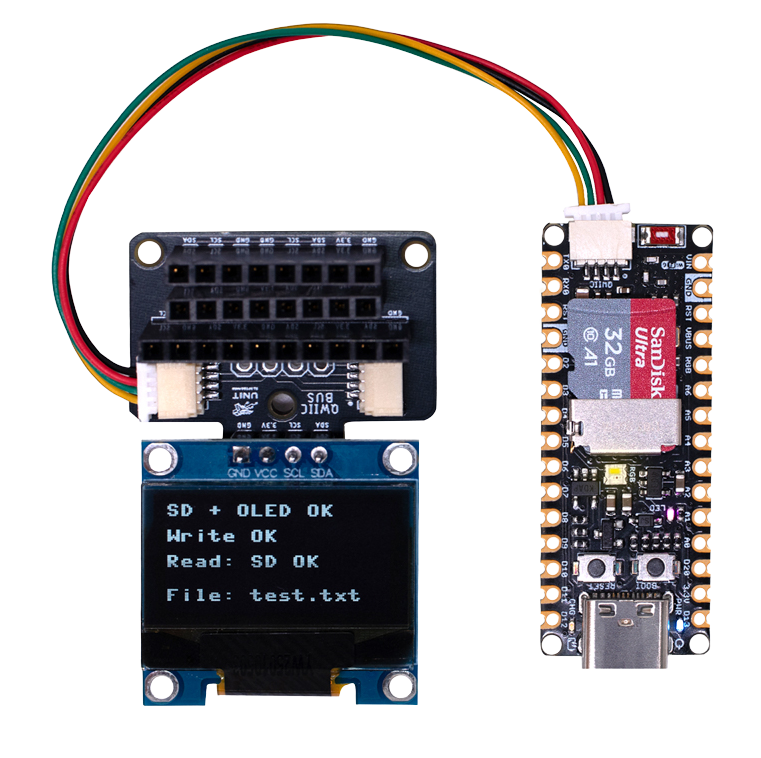
Fig. 17 I2C Device Connection Example#
Scanning for I2C Devices#
To scan for I2C devices connected to the bus, you can use the following code snippet:
import machine

# PULSAR H2 I2C pins: A4 (SDA) = GPIO12, A5 (SCL) = GPIO22
i2c = machine.I2C(0, scl=machine.Pin(22), sda=machine.Pin(12))
devices = i2c.scan()

for device in devices:
    print("Device found at address: {}".format(hex(device)))
#include <Wire.h>

void setup() {
  // PULSAR H2 I2C pins: A4 (SDA) = GPIO12, A5 (SCL) = GPIO22
  Wire.setSDA(12);
  Wire.setSCL(22);
  Wire.begin();
  Serial.begin(9600); // Start serial communication at 9600 baud rate
  while (!Serial); // Wait for serial port to connect
  Serial.println("\nI2C Scanner");
}

void loop() {
  byte error, address;
  int nDevices;

  Serial.println("Scanning...");

  nDevices = 0;
  for(address = 1; address < 127; address++ ) {
    // The i2c_scanner uses the return value of the Write.endTransmisstion to see if
    // a device did acknowledge to the address.
    Wire.beginTransmission(address);
    error = Wire.endTransmission();

    if (error == 0) {
      Serial.print("I2C device found at address 0x");
      if (address<16)
        Serial.print("0");
      Serial.print(address, HEX);
      Serial.println("  !");

      nDevices++;
    }
    else if (error==4) {
      Serial.print("Unknown error at address 0x");
      if (address<16)
        Serial.print("0");
      Serial.println(address, HEX);
    }
  }
  if (nDevices == 0)
    Serial.println("No I2C devices found\n");
  else
    Serial.println("done\n");

  delay(5000);           // wait 5 seconds for next scan
}
SSD1306 Display#
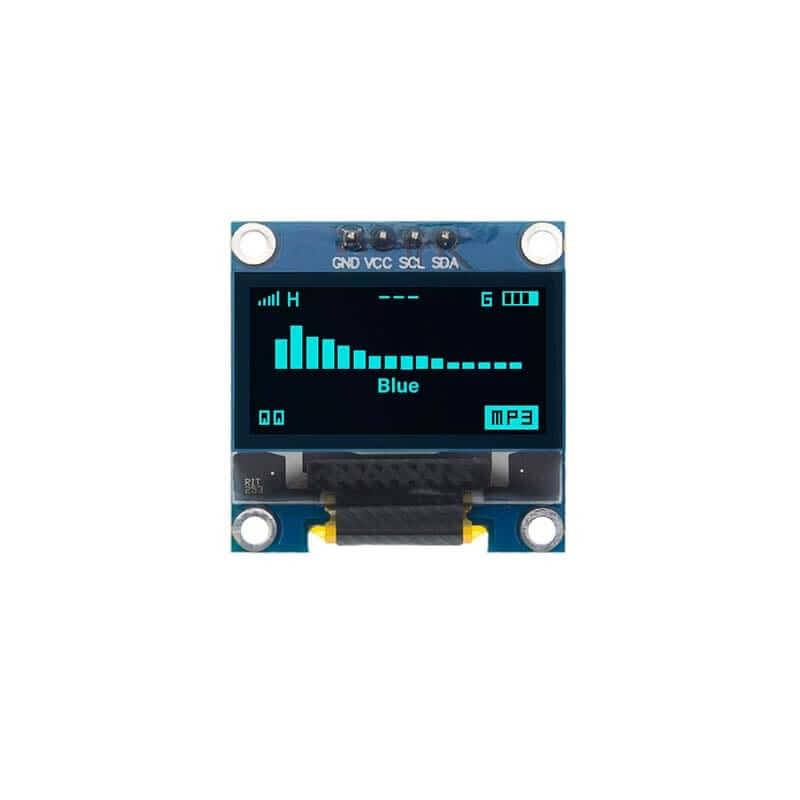
Fig. 18 SSD1306 Display#
The display 128x64 pixel monochrome OLED display equipped with an SSD1306 controller is connected using a JST 1.25mm 4-pin connector. The following table provides the pinout details for the display connection.
Pin |
Connection |
|---|---|
1 |
GND |
2 |
VCC |
3 |
SDA |
4 |
SCL |
Library Support#
The ocks.py library for MicroPython on ESP32 & RP2040 is compatible with the SSD1306 display controller.
Installation
Open Thonny.
Navigate to Tools -> Manage Packages.
Search for
ocksand click Install.
Alternatively, download the library from ocks.py.
Microcontroller Configuration
SoftI2C(scl, sda, *, freq=400000, timeout=50000)
Change the following line depending on your microcontroller:
For PULSAR H2 (ESP32-H2):
>>> i2c = machine.SoftI2C(freq=400000, timeout=50000, sda=machine.Pin(12), scl=machine.Pin(22))
Example Code
import machine
from ocks import SSD1306_I2C

# PULSAR H2 I2C pins: A4 (SDA) = GPIO12, A5 (SCL) = GPIO22
i2c = machine.SoftI2C(freq=400000, timeout=50000, sda=machine.Pin(12), scl=machine.Pin(22))

oled = SSD1306_I2C(128, 64, i2c)

# Fill the screen with white and display
oled.fill(1)
oled.show()

# Clear the screen (fill with black)
oled.fill(0)
oled.show()

# Display text
oled.text('UNIT', 50, 10)
oled.text('ELECTRONICS', 25, 20)
oled.show()
Replace sda=machine.Pin(*) and scl=machine.Pin(*) with the appropriate GPIO pins for your setup.
The Adafruit_SSD1306 library for Arduino is compatible with the SSD1306 display controller.
Installation
Open the Arduino IDE.
Navigate to Tools -> Manage Libraries.
Search for
Adafruit_SSD1306and click Install.
Example Code
#include <Wire.h>
#include <Adafruit_GFX.h>
#include <Adafruit_SSD1306.h>

// OLED display TWI (I2C) interface
#define OLED_RESET     -1 // Reset pin # (or -1 if sharing Arduino reset pin)
#define SCREEN_WIDTH   128 // OLED display width, in pixels
#define SCREEN_HEIGHT  64  // OLED display height, in pixels
#define SDA_PIN        4   // SDA pin
#define SCL_PIN        5   // SCL pin

// Declare an instance of the class (specify width and height)
Adafruit_SSD1306 display(SCREEN_WIDTH, SCREEN_HEIGHT, &Wire, OLED_RESET);

void setup() {
  Serial.begin(9600);

  // Initialize I2C - PULSAR H2 pins: A4 (SDA) = GPIO12, A5 (SCL) = GPIO22

  Wire.begin(12,22);
  // Start the OLED display
  if(!display.begin(SSD1306_SWITCHCAPVCC, 0x3C)) { // Address 0x3C for 128x64
    Serial.println(F("SSD1306 allocation failed"));
    for(;;); // Don't proceed, loop forever
  }

  // Clear the buffer
  display.clearDisplay();

  // Set text size and color
  display.setTextSize(1);
  display.setTextColor(SSD1306_WHITE);
  display.setCursor(0,0);
  display.println(F("UNIT ELECTRONICS!"));
  display.display();  // Show initial text
  delay(4000);        // Pause for 2 seconds
}

void loop() {
  // Increase a counter
  static int counter = 0;

  // Clear the display buffer
  display.clearDisplay();
  display.setCursor(0, 10); // Position cursor for new text
  display.setTextSize(2);   // Larger text size

  // Display the counter
  display.print(F("Count: "));
  display.println(counter);

  // Refresh the display to show the new count
  display.display();

  // Increment the counter
  counter++;

  // Wait for half a second
  delay(500);
}
#include "ssd1306.h"
#include "driver/i2c.h"
#include "esp_log.h"

#define I2C_MASTER_NUM I2C_NUM_0
#define I2C_MASTER_SDA_IO 12  // PULSAR H2 A4 (SDA) = GPIO12
#define I2C_MASTER_SCL_IO 22  // PULSAR H2 A5 (SCL) = GPIO22
#define I2C_MASTER_FREQ_HZ 100000

static const char *TAG = "MAIN";

void scan_i2c_bus(void) {
   ESP_LOGI(TAG, "Scanning I2C bus...");
   for (uint8_t addr = 1; addr < 127; addr++) {
      i2c_cmd_handle_t cmd = i2c_cmd_link_create();
      i2c_master_start(cmd);
      i2c_master_write_byte(cmd, (addr << 1) | I2C_MASTER_WRITE, true);
      i2c_master_stop(cmd);
      esp_err_t ret = i2c_master_cmd_begin(I2C_MASTER_NUM, cmd, 100 / portTICK_PERIOD_MS);
      i2c_cmd_link_delete(cmd);
      if (ret == ESP_OK) {
        ESP_LOGI(TAG, "Found device at 0x%02X", addr);
      }
   }
   ESP_LOGI(TAG, "Scan complete.");
}

void app_main(void) {
   i2c_config_t conf = {
      .mode = I2C_MODE_MASTER,
      .sda_io_num = I2C_MASTER_SDA_IO,
      .scl_io_num = I2C_MASTER_SCL_IO,
      .sda_pullup_en = GPIO_PULLUP_ENABLE,
      .scl_pullup_en = GPIO_PULLUP_ENABLE,
      .master.clk_speed = I2C_MASTER_FREQ_HZ,
   };

   i2c_param_config(I2C_MASTER_NUM, &conf);
   i2c_driver_install(I2C_MASTER_NUM, conf.mode, 0, 0, 0);

   scan_i2c_bus(); // Optional

   ssd1306_init(I2C_MASTER_NUM);
   ssd1306_clear(I2C_MASTER_NUM);
   ssd1306_draw_text(I2C_MASTER_NUM, 0, "ESP32-H2 ");
   ssd1306_draw_text(I2C_MASTER_NUM, 2, "I2C Scan + OLED");
   ssd1306_draw_text(I2C_MASTER_NUM, 4, "Monosaurio");
}