Analog to Digital Conversion#
Learn how to read analog sensor values using the ADC module on the PULSAR H2 development board with the ESP32-H2. This section will cover the basics of analog input and conversion techniques.
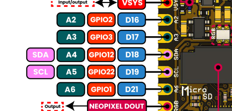
Fig. 15 ADC Pins#
ADC Definition#
Analog-to-digital conversion (ADC) is a process that converts analog signals into digital values. The ESP32-H2, equipped with multiple ADC channels, provides flexible options for reading analog voltages and converting them into digital values. Below, you will find the details on how to utilize these pins for ADC operations.
Quantification and Codification of Analog Signals#
Analog signals are continuous signals that can take on any value within a given range. Digital signals, on the other hand, are discrete signals that can only take on specific values. The process of converting an analog signal into a digital signal involves two steps: quantification and codification.
Quantification: This step involves dividing the analog signal into discrete levels. The number of levels determines the resolution of the ADC. For example, a 12-bit ADC can divide the analog signal into 4096 levels.
Codification: This step involves assigning a digital code to each quantization level. The digital code represents the value of the analog signal at that level.
ESP32-H2 ADC Channels (Official Documentation)#
Complete ADC channel mapping according to ESP32-H2 official documentation:
GPIO Pin |
ADC Channel |
Description |
|---|---|---|
GPIO0 |
ADC1_CH0 |
12-bit SAR ADC, Channel 0 |
GPIO2 |
ADC1_CH1 |
12-bit SAR ADC, Channel 1 |
GPIO3 |
ADC1_CH2 |
12-bit SAR ADC, Channel 2 |
GPIO4 |
ADC1_CH3 |
12-bit SAR ADC, Channel 3 |
GPIO5 |
ADC1_CH4 |
12-bit SAR ADC, Channel 4 |
ADC Pin Status on PULSAR H2#
PULSAR H2 Pin |
ESP32-H2 GPIO |
ADC Status |
ADC Channel |
Notes / Alternative Function |
|---|---|---|---|---|
A0/D14 |
N/C |
NO |
— |
Battery control circuit (not connected to MCU) |
A1/D15 |
N/C |
NO |
— |
System voltage monitoring (not connected to MCU) |
A2/D16 |
GPIO2 |
YES |
ADC1_CH1 |
Available for analog readings |
A3/D17 |
GPIO3 |
YES |
ADC1_CH2 |
Available for analog readings |
A4 (SDA) |
GPIO12 |
YES |
ADC Capable |
I2C SDA + ADC support (JST connector) |
A5 (SCL) |
GPIO22 |
YES |
ADC Capable |
I2C SCL + ADC support (JST connector) |
A6 |
GPIO1 |
YES |
ADC1_CH0 |
Available for analog readings |
A7 |
N/C |
NO |
— |
NeoPixel (WS2812B) output pin |
Warning
Pin Usage Notes:
A0 and A1: These are NOT connected to the ESP32-H2 microcontroller
A2, A3, A6: Dedicated analog pins - best for ADC readings
A4 and A5: Dual function (I2C + ADC) - available on JST connector
A7: This is for NeoPixel output, not analog input
A2, A3, A4, A5, and A6 work for analog readings!
Summary Table: Usable ADC Pins#
Important
5 pins can be used for analog readings on PULSAR H2:
Pin Label |
GPIO |
ADC Channel |
Notes |
|---|---|---|---|
A2 |
GPIO2 |
ADC1_CH1 |
Dedicated analog pin |
A3 |
GPIO3 |
ADC1_CH2 |
Dedicated analog pin |
A4 (SDA) |
GPIO12 |
ADC Capable |
I2C SDA + ADC (JST connector) |
A5 (SCL) |
GPIO22 |
ADC Capable |
I2C SCL + ADC (JST connector) |
A6 |
GPIO1 |
ADC1_CH0 |
Dedicated analog pin |
Note
ADC Summary:
ESP32-H2 chip: Has 5 ADC channels (GPIO0, GPIO1, GPIO2, GPIO3, GPIO4, GPIO5)
PULSAR H2 board: 5 ADC pins are usable (A2, A3, A4, A5, A6)
Resolution: 12-bit (0-4095 values)
Voltage Range: 0V to 3.3V
Important
I2C vs ADC on A4/A5: You can use A4 and A5 for ADC readings when not using I2C. If you need both I2C and ADC, use A2/A3 for ADC and A4/A5 for I2C.
Class ADC#
The machine.ADC class is used to create ADC objects that can interact with the analog pins.
- class machine.ADC(pin)#
The constructor for the ADC class takes a single argument: the pin number.
ADC Pin Usage Examples#
Use only A2 (GPIO2) or A3 (GPIO3) for analog readings:
import machine

# ADC pins available on PULSAR H2:
adc_a2 = machine.ADC(machine.Pin(2))   # A2 - ADC1_CH1 (dedicated)
adc_a3 = machine.ADC(machine.Pin(3))   # A3 - ADC1_CH2 (dedicated)
adc_a4 = machine.ADC(machine.Pin(12))  # A4 - GPIO12 (SDA + ADC)
adc_a5 = machine.ADC(machine.Pin(22))  # A5 - GPIO22 (SCL + ADC)
adc_a6 = machine.ADC(machine.Pin(1))   # A6 - ADC1_CH0 (dedicated)
// ADC pins available on PULSAR H2:
#define ADC_PIN_A2  2   // GPIO2 (A2) - ADC1_CH1 (dedicated)
#define ADC_PIN_A3  3   // GPIO3 (A3) - ADC1_CH2 (dedicated)
#define ADC_PIN_A4  12  // GPIO12 (A4) - SDA + ADC (JST connector)
#define ADC_PIN_A5  22  // GPIO22 (A5) - SCL + ADC (JST connector)
#define ADC_PIN_A6  1   // GPIO1 (A6) - ADC1_CH0 (dedicated)
Reading Values#
To read the analog value converted to a digital format:
adc_value = adc.read()  # Read the ADC value
print(adc_value)  # Print the ADC value
voltage = analogRead(ADC_PIN);
Example Code#
Below is an example that continuously reads from an ADC pin and prints the results:
import machine
import time

# Setup - All available ADC pins on PULSAR H2
adc_a2 = machine.ADC(machine.Pin(2))   # A2 - dedicated ADC
adc_a3 = machine.ADC(machine.Pin(3))   # A3 - dedicated ADC
adc_a4 = machine.ADC(machine.Pin(12))  # A4 - SDA + ADC (JST)
adc_a5 = machine.ADC(machine.Pin(22))  # A5 - SCL + ADC (JST)
adc_a6 = machine.ADC(machine.Pin(1))   # A6 - dedicated ADC

# Continuous reading from all ADC pins
while True:
    # Read all ADC pins
    value_a2 = adc_a2.read_u16()
    value_a3 = adc_a3.read_u16()
    value_a4 = adc_a4.read_u16()
    value_a5 = adc_a5.read_u16()
    value_a6 = adc_a6.read_u16()

    # Convert to voltages
    voltage_a2 = (value_a2 / 65535) * 3.3
    voltage_a3 = (value_a3 / 65535) * 3.3
    voltage_a4 = (value_a4 / 65535) * 3.3
    voltage_a5 = (value_a5 / 65535) * 3.3
    voltage_a6 = (value_a6 / 65535) * 3.3

    print(f"A2: {voltage_a2:.2f}V | A3: {voltage_a3:.2f}V | A4: {voltage_a4:.2f}V | A5: {voltage_a5:.2f}V | A6: {voltage_a6:.2f}V")
    time.sleep(1)
// Only these pins work for ADC on PULSAR H2
const int adcPin_A2 = 2; // GPIO2 (A2) - ADC1_CH1
const int adcPin_A3 = 3; // GPIO3 (A3) - ADC1_CH2

void setup() {
  Serial.begin(115200);
  analogReadResolution(12); // Set resolution to 12-bit (0-4095)
  delay(1000);
  Serial.println("PULSAR H2 ADC Test - Only A2 and A3 work!");
}

void loop() {
  // Read from A2
  int value_A2 = analogRead(adcPin_A2);
  float voltage_A2 = (value_A2 / 4095.0) * 3.3;

  // Read from A3
  int value_A3 = analogRead(adcPin_A3);
  float voltage_A3 = (value_A3 / 4095.0) * 3.3;

  // Print results
  Serial.print("A2: "); Serial.print(value_A2);
  Serial.print(" ("); Serial.print(voltage_A2); Serial.print("V) | ");
  Serial.print("A3: "); Serial.print(value_A3);
  Serial.print(" ("); Serial.print(voltage_A3); Serial.println("V)");

  delay(1000);
}
#include <stdio.h>
#include "esp_log.h"
#include "esp_err.h"
#include "freertos/FreeRTOS.h"
#include "freertos/task.h"
#include "esp_adc/adc_oneshot.h"

static const char *TAG = "ADC_MIN";

void app_main(void)
{
    adc_oneshot_unit_handle_t adc_handle;
    adc_oneshot_unit_init_cfg_t init_cfg = {
        .unit_id = ADC_UNIT_1,
    };
    ESP_ERROR_CHECK(adc_oneshot_new_unit(&init_cfg, &adc_handle));

    adc_oneshot_chan_cfg_t chan_cfg = {
        .bitwidth = ADC_BITWIDTH_DEFAULT,
        .atten = ADC_ATTEN_DB_12,  // <- Usa el recomendado
    };
    ESP_ERROR_CHECK(adc_oneshot_config_channel(adc_handle, ADC_CHANNEL_2, &chan_cfg)); // GPIO2

    int adc_raw;
    while (1) {
        ESP_ERROR_CHECK(adc_oneshot_read(adc_handle, ADC_CHANNEL_2, &adc_raw));
        ESP_LOGI(TAG, "Lectura ADC (GPIO2): %d", adc_raw);
        vTaskDelay(pdMS_TO_TICKS(1000));  // <- Necesitabas incluir FreeRTOS
    }
}