RP2040 Firmware#
Firmware update#
Note
The contents of this chapter are hosted in the unit_ch55x_docker_sdk.git repository. Always remember to keep Docker Desktop open in your computer; otherwise, the commands will not work properly.
To start using your Multi-Protocol Programmer as a PICO DAP, follow these steps:
cd unit_ch55x_docker_sdk
Once you are at the main directory, open a terminal and enter the commands:
Linux#
./spkg/spkg -p ./examples/USB/Prog/PICO-DAP
Windows#
./spkg/spkg.bat -p ./examples/USB/Prog/PICO-DAP
The command creates a .bin file inside the build folder.
WCHIspStudio#
Then open WCHIspStudio to upload the firmware
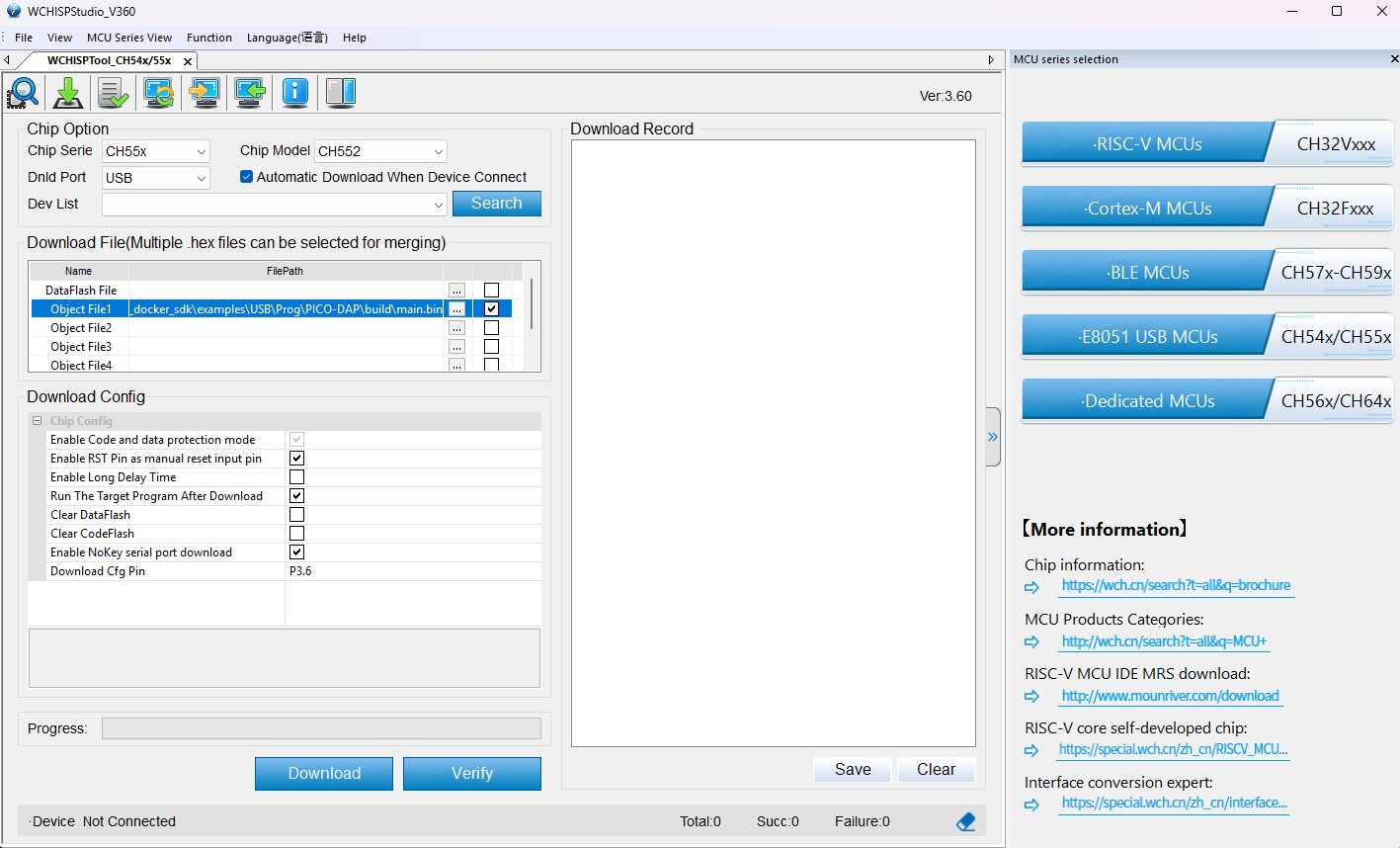
Settings WCHIspStudio
In Object File 1 make sure to enter the correct path to the directory with the firmware.
Make sure the “Automatic Download When Device Connect” option is enabled.
To add the path you have to click on this bottom “…” and check.
Warning
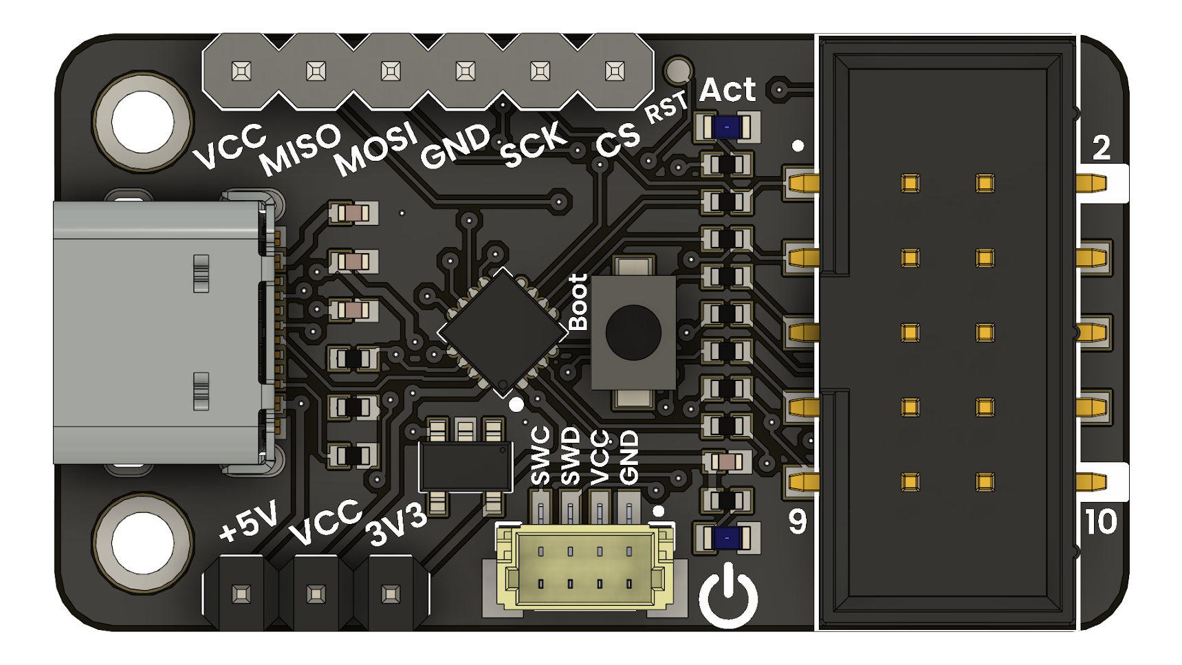
Before connecting your Multi-Protocol Programmer, make sure to power it with +5V. You can do this by setting your switch to +5V.
Push the Boot bottom and connect your Multi-Protocol Programmer to your computer.
Wait until de firmware has finished updating your device.
Done! Now you can use your UNIT CH552 Multi-Protocol Programmer!
Create a new project in Pico SDK#
Installation#
Open Visual Studio Code, in the extensions menu, search Raspeberry Pi Pico:
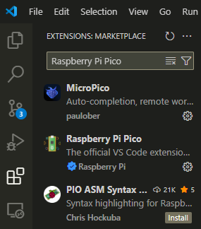
Extension menu
And install the official version from Raspberry:
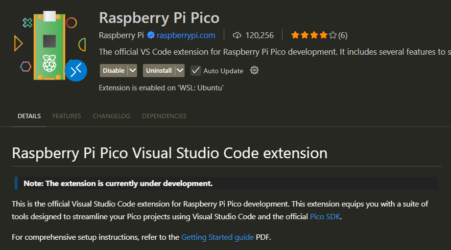
Pico SDK
In the Activity Bar, you will find the icon of your new extension in Visual Studio Code.
In the general menu, click on “New C/C++ Project”
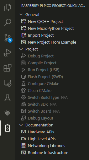
General menu
Once the project is created, you will need to configure it. For this example, we will use a Raspberry Pico, UART, SPI and Console over UART and USB
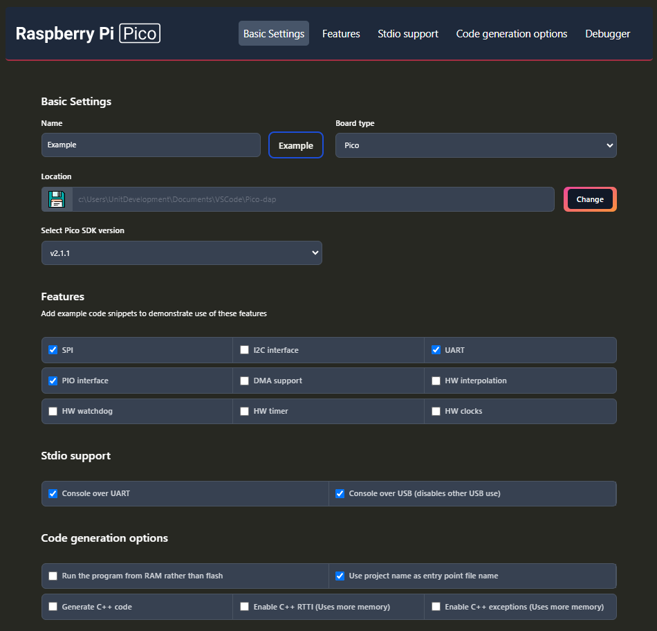
Basic configuration
Project#
Inside the generated project, you will find these files.
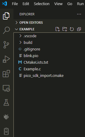
Files generated
Open the .c file, here we can change or modify the source code.
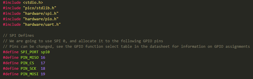
Source code
Examples#
Here are some examples for a Raspeberry Pi Pico:
Hello, World! Open a serial monitor and see what’s happening!
#include <stdio.h>
#include "pico/stdlib.h"
#include "hardware/uart.h"

// UART defines
// By default the stdout UART is uart0, so we will use the second one
#define UART_ID uart1
#define BAUD_RATE 115200

// Use pins 4 and 5 for UART1
// Pins can be changed, see the GPIO function select table in the datasheet for information on GPIO assignments
#define UART_TX_PIN 4
#define UART_RX_PIN 5


int main()
{
    stdio_init_all();

    // Set up our UART
    uart_init(UART_ID, BAUD_RATE);
    // Set the TX and RX pins by using the function select on the GPIO
    // Set datasheet for more information on function select
    gpio_set_function(UART_TX_PIN, GPIO_FUNC_UART);
    gpio_set_function(UART_RX_PIN, GPIO_FUNC_UART);

    // Use some the various UART functions to send out data
    // In a default system, printf will also output via the default UART

    // Send out a string, with CR/LF conversions
    uart_puts(UART_ID, " Hello, UART!\n");

    // For more examples of UART use see https://github.com/raspberrypi/pico-examples/tree/master/uart

    while (true) {
        printf("Hello, World!\n");
        sleep_ms(1000);
    }
}
Blink
#include <stdio.h>
#include "pico/stdlib.h"
#include "hardware/uart.h"

// UART configuration
#define UART_ID uart1
#define BAUD_RATE 115200
#define UART_TX_PIN 4
#define UART_RX_PIN 5

// On-board LED pin (GPIO 25)
#define LED_PIN 25

int main()
{
    // Initialize standard I/O (required for printf to work)
    stdio_init_all();

    // Initialize UART1 with the specified baud rate
    uart_init(UART_ID, BAUD_RATE);

    // Configure UART TX and RX GPIO functions
    gpio_set_function(UART_TX_PIN, GPIO_FUNC_UART);
    gpio_set_function(UART_RX_PIN, GPIO_FUNC_UART);

    // Initialize GPIO 25 for LED and set it as output
    gpio_init(LED_PIN);
    gpio_set_dir(LED_PIN, GPIO_OUT);

    // Send a welcome message through UART1
    uart_puts(UART_ID, " Hello, UART!\n");

    while (true) {
        // Turn on the LED
        gpio_put(LED_PIN, 1);
        uart_puts(UART_ID, "LED ON\n");  // Send status via UART
        sleep_ms(500);                   // Wait 500 milliseconds

        // Turn off the LED
        gpio_put(LED_PIN, 0);
        uart_puts(UART_ID, "LED OFF\n"); // Send status via UART
        sleep_ms(500);                   // Wait another 500 milliseconds
    }
}
Flashing#
Once you have your example ready to upload, just click on the Pico SDK icon on the Activity Bar.
Select the “Flash Project (SWD)” option.
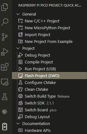
Source code
Note
To program a Raspberry Pico, use the SWD protocol. For more information, check the pinout.
Warning
The Raspberry Pi Pico operates at 3.3V. Switch to 3.3V before connecting your device.