STM32 Firmware#
Firmware update#
Note
The contents of this chapter are hosted in the unit_ch55x_docker_sdk.git repository. Always remember to keep Docker Desktop open in your computer; otherwise, the commands will not work properly.
To start using your Multi-Protocol Programmer as a PICO DAP, follow these steps:
cd unit_ch55x_docker_sdk
Once you are at the main directory, open a terminal and enter the commands:
Linux#
./spkg/spkg -p ./examples/USB/Prog/PICO-DAP
Windows#
./spkg/spkg.bat -p ./examples/USB/Prog/PICO-DAP
The command creates a .bin file inside the build folder.
WCHIspStudio#
Then open WCHIspStudio to upload the firmware
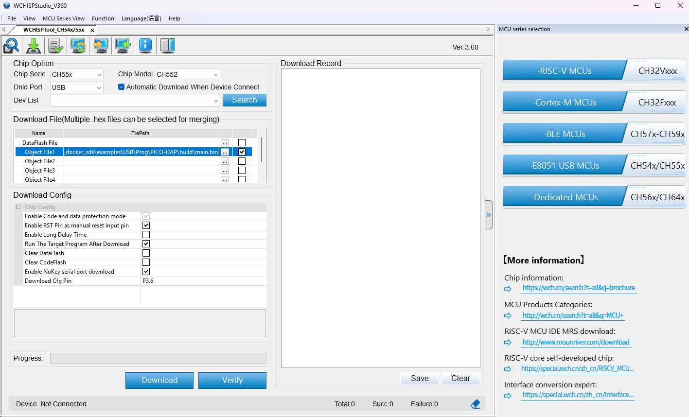
Settings WCHIspStudio
In Object File 1 make sure to enter the correct path to the directory with the firmware.
Make sure the “Automatic Download When Device Connect” option is enabled.
To add the path you have to click on this bottom “…” and check.
Warning
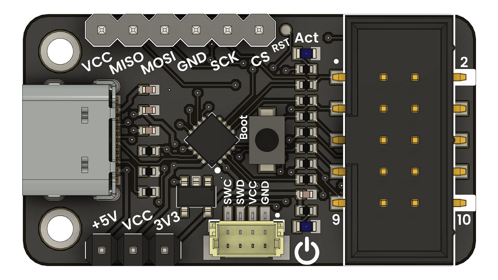
Before connecting your Multi-Protocol Programmer, make sure to power it with +5V. You can do this by setting your switch to +5V.
Push the Boot bottom and connect your Multi-Protocol Programmer to your computer.
Wait until de firmware has finished updating your device.
Done! Now you can use your UNIT CH552 Multi-Protocol Programmer!
Create a new project in PlatformIO#
Installation#
Open Visual Studio Code, in the extensions menu, search PlatformIO:
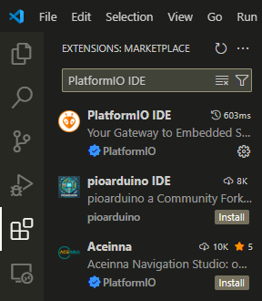
PlatformIO extension in Visual Studio Code
And install the official version from PlatformIO:
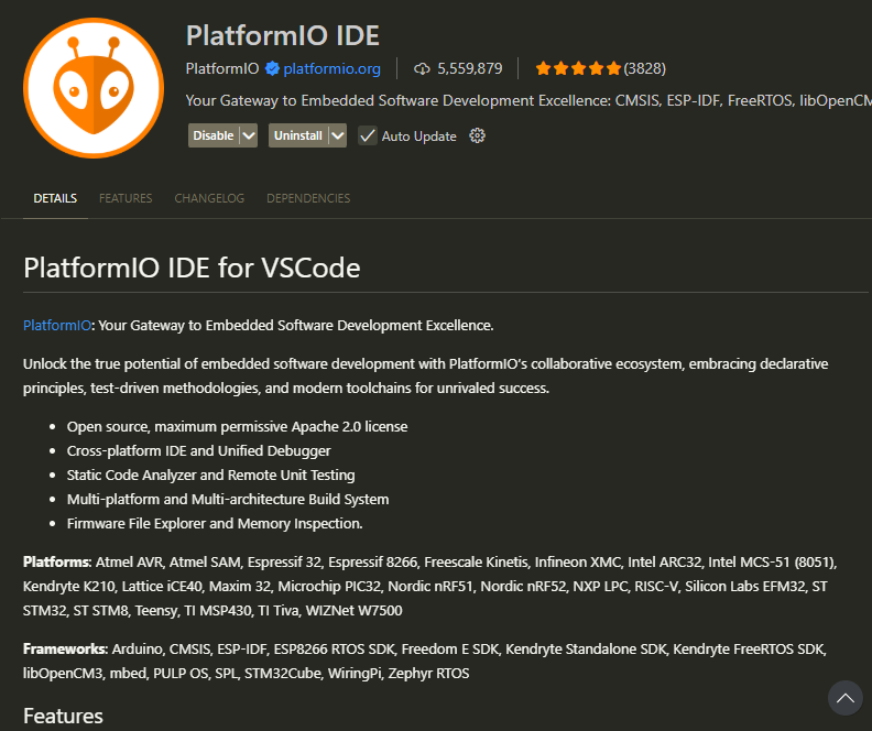
PlatformIO extension
In the Activity Bar, you will find the icon of your new extension in Visual Studio Code.
In the general menu, click on “Create New Project”
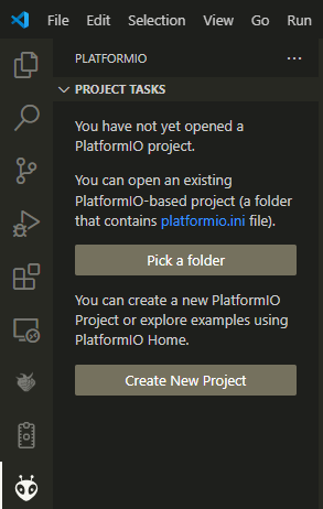
General menu
In the Quick Access menu, we can open an existing file for our STM32F4xx or create a new one:
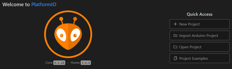
Quick Access menu
Next, in the Project Wizard:
We will name our file.
Select the specific model of our STM32F4xx board.
Choose the framework (for this example, we will use CMSIS)
Specify the location where we want to save the project.
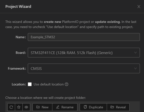
Project Wizard
Project#
Inside the generated project, you will find this project structure.
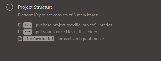
Project structure
If you need to change your COM port, follow these steps:
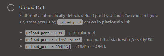
New COM port
Inside the .ini file, make sure you have this configuration:
[env:blackpill_f411ce]
platform = ststm32
board = blackpill_f411ce
framework = cmsis
upload_protocol = cmsis-dap
debug_tool = cmsis-dap
Note
If you are using a different board, change the “[env: …]” and “board = …” to match your board model.
Here is a list of common STM32 microcontrollers and their corresponding board identifiers used in PlatformIO’s platformio.ini file.
Microcontroller / Board |
PlatformIO board name |
|---|---|
STM32F103C8 (Blue Pill) |
|
STM32F401RE (Nucleo) |
|
STM32F446RE (Nucleo) |
|
STM32F103RB |
|
STM32F407VG (Discovery) |
|
STM32F411CEU6 (Blackpill) |
|
Example#
The following example is a Blink using GPIOC (PC13) as an output.
#include "stm32f4xx.h"

// Simple software delay loop
void delay(volatile uint32_t t) {
    while (t--);
}

int main(void) {
    // 1. Enable the clock for GPIOC (required before accessing GPIOC registers)
    RCC->AHB1ENR |= RCC_AHB1ENR_GPIOCEN;

    // 2. Configure pin PC13 as general-purpose output (MODER13 = 0b01)
    GPIOC->MODER &= ~(0x3 << (13 * 2)); // Clear MODER13 bits
    GPIOC->MODER |=  (0x1 << (13 * 2)); // Set MODER13 to output mode

    // 3. Main loop
    while (1) {
        GPIOC->ODR ^= (1 << 13); // Toggle PC13 (invert LED state)
        delay(500000);           // Simple delay (not accurate, for testing purposes)
    }
}
Flashing#
Once you have your example ready to upload, just click on the PlatformIO icon on the Activity Bar.
Select the “Upload” option.
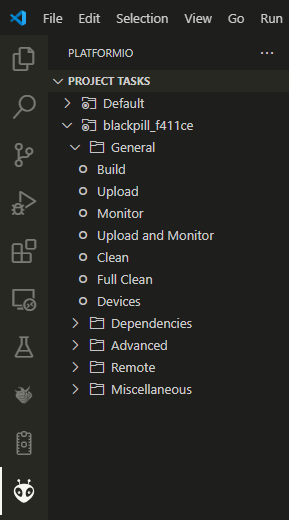
Flashing
Note
To program a STM32F4xx, use the SWD protocol. For more information, check the pinout.
Warning
The STM32F4xx operates at 3.3V. Switch to 3.3V before connecting your device.